3D rebar detailing is the BIM-based creation of constructible reinforcement models and shop drawings that drive fabrication and field placement. At 370 New Enterprise Way in Woodbridge, Dass Rebar uses 3D detailing to coordinate bar lists, bends, couplers, and placement sequences, which reduces rework and compresses schedules on Ontario projects.
By Navjot Dass • Last updated: 2026-06-07
Overview and table of contents
This guide explains what 3D rebar detailing is, why it matters, and how it works end-to-end—from takeoff to shop drawings, fabrication, delivery, and on-site assembly. You’ll see best practices, tools, local considerations, and real examples from Ontario jobs supported by Dass Rebar’s integrated services.
Here’s how to navigate this complete guide quickly.
- What is 3D rebar detailing?
- Why it matters for Ontario builders
- How the process works (step-by-step)
- Types, methods, and model approaches
- Best practices our team follows
- Tools and resources
- Case studies and examples
- Frequently Asked Questions
- Key takeaways
- Conclusion and next steps
What is 3D rebar detailing?
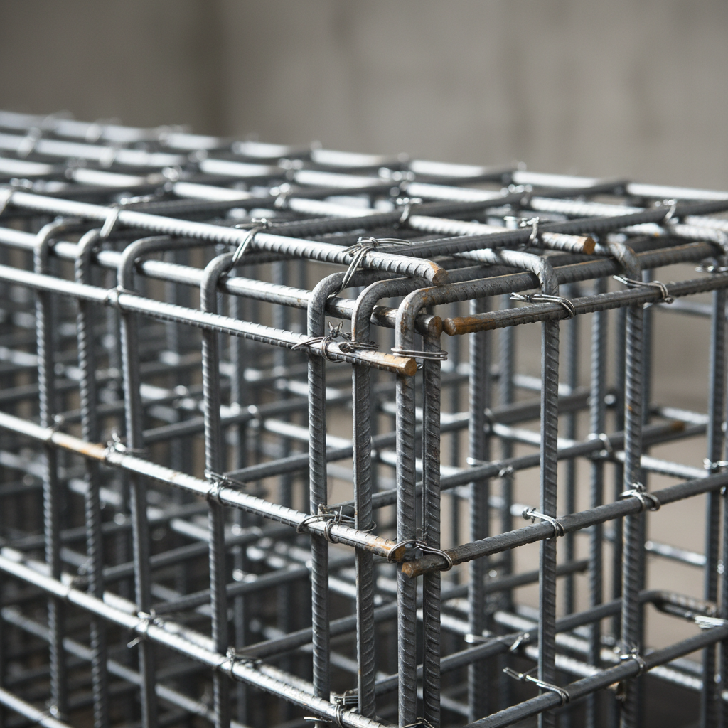
3D rebar detailing is the practice of modeling reinforcement in three dimensions to produce constructible shop drawings, bar lists, and bending schedules. It translates design intent into field-ready instructions, coordinating bar sizes, shapes, splices, laps, and couplers to ensure accurate fabrication and hassle-free placement.
In simple terms, 3D rebar detailing turns structural drawings into a buildable plan for steel inside the concrete. Unlike flat 2D sheets, the model shows every bar’s location, length, and bend, including congestion at columns, beams, and slabs. That clarity helps foremen, placers, and inspectors move faster with fewer questions.
At Dass Rebar, 3D modeling ties directly to in-house estimating, shop drawings and detailing, and fabrication workflows. The same data then fuels supply and delivery coordination so material lands on-site aligned to pour sequences.
Why 3D rebar detailing matters (Ontario focus)
3D rebar detailing prevents clashes, clarifies placement, and streamlines inspections, which protects schedules across Woodbridge and the Regional Municipality of York. When models drive drawings, bar marks match reality, deliveries align to pours, and field crews spend more time placing and less time resolving conflicts.
Why does this matter to you? Coordination errors snowball on-site. When a congested beam-column joint isn’t resolved on paper, crews improvise in the field. That creates waste, slows pours, and can trigger rework. A coordinated model resolves spacing, cover, and lap conditions before steel is cut or bent.
For Ontario builders working with epoxy-coated bar, GFRB, or large-format mesh, model-driven schedules simplify inspection and QA. Our team links the model to delivery tags so bundles arrive organized by zone and sequence, reducing handling and wait time at the deck.
How 3D rebar detailing works (step-by-step)
The 3D detailing workflow moves from intake and model setup to bar modeling, reviews, shop drawings, and release to fabrication. Each gate—design coordination, constructability checks, and sequencing—reduces surprises and keeps procurement, trucking, and placement in sync with the pour plan.
Process at a glance
- Project intake and scope: gather structural drawings, specifications, addenda, and target pour dates; align on tolerances and coupler systems.
- Model setup: establish levels, grids, cover, preferred splice strategy, and naming conventions for bar marks.
- Bar modeling: place bars, stirrups, ties, and mats; resolve congestion at beams, cores, and transfer slabs.
- Coordination checks: run clash reviews; confirm embed, PT duct, opening, and sleeve clearances.
- Shop drawings + lists: publish marked sheets, bending schedules, and bundle maps for zones/sequences.
- Fabrication release: issue cut/bend data to the shop; barcode bundles for tracking.
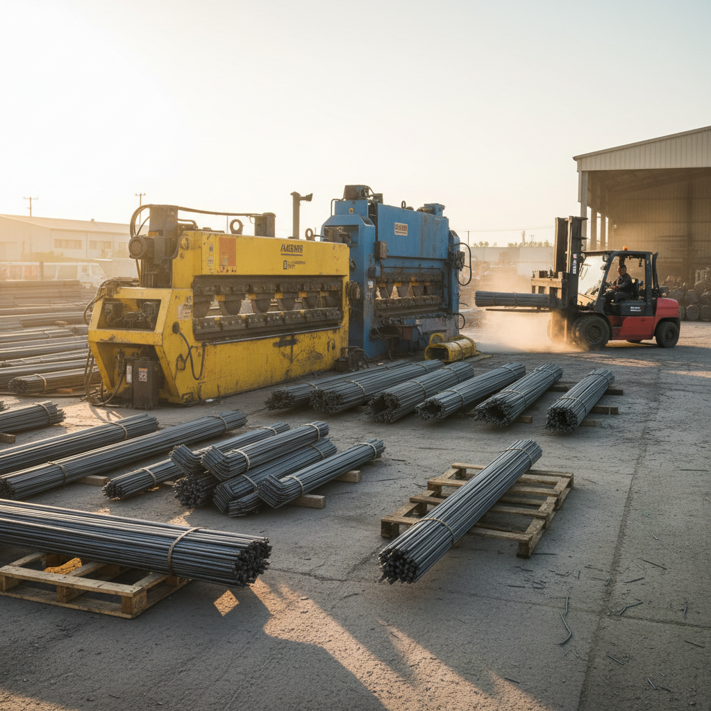
- Delivery + placement: align trucking with pour windows and crane time; feed as-built updates back to the model.
| Stage | Main output | Who acts | Quality gate |
|---|---|---|---|
| Intake | Scope + milestones | GC, engineer, Dass Rebar PM | Documents complete; dates aligned |
| Modeling | 3D bars placed | Detailer | Cover/spacing checks |
| Review | Clash list resolved | Detailer + site | Sign-off to issue |
| Issuance | Shop drawings + lists | Dass Rebar | Revision control |
| Fabrication | Cut/bent bars | Shop | Sample bend verification |
| Delivery | Sequenced bundles | Dispatch + drivers | Zone/sequence labels |
To keep the entire chain tight, we pair model-driven drawings with coordinated logistics. See our estimating guide for how quantities and zones are planned early, and how that planning ties into fabrication workflows and on-time delivery windows.
Types, methods, and approaches
3D rebar models range from coordination-grade to fabrication-grade detail. Approaches include element-level mats for slabs, bar-by-bar modeling for congested nodes, and coupler-first strategies for spliced columns. The right method balances constructability, schedule, and model effort.
Model granularity and use-cases
- Coordination-grade: focus on bar zones and mats to validate spacing, cover, and penetrations in repetitive areas like flat slabs.
- Fabrication-grade: bar-by-bar modeling with exact bends, hooks, and splices—ideal for cores, transfer beams, and podium slabs.
- Coupler-first: model couplers before bars to lock splice locations at column stacks and walls where lap lengths are constrained.
- Material variants: include epoxy-coated reinforcing, GFRB, and welded wire mesh layouts with correct lap/overlap rules.
2D vs 3D detailing at a glance
| Aspect | Traditional 2D | 3D Detailing |
|---|---|---|
| Clash detection | Manual checks; issues emerge on-site | Visual clashes resolved before fabrication |
| Bar lists | Typed or CAD-extracted | Model-driven, auto-coordinated |
| Delivery sequencing | Spreadsheet-based | Aligned to zones and pours from model |
| QA/inspection | Interpretation-heavy | Clear visuals reduce ambiguity |
For deeper reinforcement basics, see our steel rebar guide, including common sizes such as 10m, 15m, and 20m bars and where they’re most often deployed in foundations and slabs.
Best practices for 3D rebar detailing
The most reliable 3D detailing starts with clean inputs, standard conventions, and early site feedback. Lock cover, laps, and coupler rules on day one; control revisions; and publish sequenced bar lists that match the crane plan. This prevents field improvisation and keeps pours predictable.
Our field-tested checklist
- Standardize early: confirm covers, bar grades (500W/400W), epoxy requirements, and mesh patterns (6×6 at 6/6, 9/9, 10/10).
- Model the tough spots first: beam-column joints, transfer slabs, elevator cores, and shear walls—resolve congestion before mass modeling.
- Sequence by pour: organize bar marks and bundles by zone/pour; print sequence tags on lists and delivery labels.
- Close the loop: feed RFIs and as-built changes back into the model; republish affected sheets quickly.
- Surface for the site: provide 3D views for foremen; include callouts for laps, hooks, and couplers where interpretation risk is high.
We pair this checklist with integrated services—detailing, cut/bend fabrication, trucking, and on-site assembly—so your plan turns into placed steel without friction.
Local considerations for Woodbridge
- Coordinate deliveries to avoid peak traffic near Queen St / Highway 50; align rebar drops with crane windows to reduce laydown congestion.
- Plan winter pours with heated enclosures; protect epoxy-coated bars from snow and ice during staging and placement.
- For jobs near Highway 50 – Zum Queen Stop EB, stage bundles by zone to minimize double-handling between curbside and the deck.
Tools and resources
Professional 3D rebar detailing relies on BIM-capable platforms plus shop-floor integration. Teams commonly use Revit-based tools, Tekla Structures, and shop systems that consume bend data, ensuring what’s modeled is exactly what the bender produces and what the crew places.
Design and coordination platforms are only half the story. Fabrication data, bundle maps, and delivery labels must align to the model. That’s why our detailing workflows feed directly into staging and trucking so bar stacks reach the right zone at the right time. For a related structural perspective, see this steel framing guide.
If your scope includes welded wire mesh, this primer on mesh types and uses pairs well with model-based slab detailing. And when schedules are tight, consider how logistics supports productivity; see insights on timely rebar delivery and sequencing strategies.
Have a congested core, transfer slab, or podium? Share your drawings and target pour dates. Our detailing team will flag high-risk areas and suggest modeling tactics to de-risk your schedule.
Case studies and examples
3D rebar detailing shines where tolerances are tight and schedules are compressed. The following Ontario scenarios show how model-first planning prevented conflicts, kept deliveries lean, and supported fast, clean placements for crews and inspectors.
High-rise podium slab (Toronto)
On The Hawthorne Residences, our team modeled heavy top/bottom mats with congested column strips. By resolving lap zones and couplers in 3D, we issued clear shop drawings and bundle maps. Deliveries were sequenced by pour strip, so crews staged once and placed without rework.
What most people don’t realize: a small decision like moving a lap past an opening can ripple through dozens of bars. In our model, those dependencies were coordinated up front, so on-site adjustments were minimal.
Townhome garages with mesh (Waterloo)
For Hickory Terraces, welded wire mesh and perimeter bars were modeled to validate overlaps and control joints. The model produced a precise mesh schedule, and our trucking fleet timed drops to match daily slab pours. Inspectors appreciated the clarity—markups aligned one-to-one with sheets.
Result: fewer layout questions and faster strip-and-rebar cycles between units, keeping the framing schedule intact.
Core walls and transfer beams (Pickering)
At The Grand at Universal City, couplers in stacked walls demanded exact splice locations. We applied a coupler-first approach in the model, then placed boundary elements and ties around those fixed points. Fabrication-grade outputs turned into predictable field placement, even with tight crane windows.
Because delivery labels matched zone/sequence language on the drawings, the site team didn’t waste time sorting bundles.
Frequently asked questions
These answers address the most common questions we hear from GCs, site supers, and concrete subcontractors about model-driven rebar detailing. Each response is concise, action-oriented, and based on our day-to-day field experience in Ontario.
What does 3D rebar detailing include?
It includes a constructible 3D model, coordinated shop drawings, bar lists, bending schedules, and bundle/sequence maps. Good deliverables also track revisions and align to pour plans so trucking and crane time are used efficiently.
How does 3D detailing reduce rework?
Clashes and lap conflicts are resolved in the model instead of on the deck. Crews receive clear, sequenced drawings and bundles. That means fewer field RFIs, cleaner inspections, and faster pours because decisions were made before steel was cut.
Do I need 3D rebar models for every pour?
Not always. Use coordination-grade models for repetitive slabs and full fabrication-grade detail for congested areas like beam-column joints, cores, and transfer zones. The right level balances effort with risk reduction.
Can 3D detailing handle epoxy-coated or GFRB bars?
Yes. Models include bar properties, lap rules, and handling notes for epoxy-coated reinforcing and GFRB. Sequenced lists and labels help crews stage and protect these materials, especially in winter conditions.
Key takeaways
Use 3D rebar detailing where congestion, couplers, or tight schedules raise risk. Standardize early, model the hot spots first, and tie drawings to delivery sequences. An integrated partner like Dass Rebar keeps modeling, fabrication, and trucking synchronized for predictable, on-time pours.
- Model early to eliminate clashes and protect pour dates.
- Publish clear, sequenced shop drawings and bar lists.
- Feed fabrication and delivery directly from the model.
- Right-size model detail by zone: coordination vs fabrication grade.
- Leverage integrated services to reduce handoffs and delays.
Conclusion and next steps
3D rebar detailing converts design intent into field certainty. When your model drives drawings, fabrication, and logistics, crews place faster, inspectors sign off sooner, and your schedule holds. Dass Rebar coordinates this loop so Ontario projects move with confidence.
Ready to de-risk your next pour? Share your drawings and target dates, and we’ll recommend where 3D detailing creates the biggest impact—cores, transfer slabs, or podiums. From there, our team will align shop drawings, foundation details, and delivery sequencing with your site plan.
Book a coordination session in Woodbridge—we’re at 370 New Enterprise Way. Our integrated estimating, detailing, fabrication, delivery, and assembly keep your reinforcing plan tight from model to placed steel.
Related articles and deeper dives
Explore these in-depth reads to connect 3D detailing with estimating, fabrication, and field execution. Each article expands one part of the workflow so your team can move from concept to pour with fewer handoffs and fewer surprises.
New to the terminology and bar sizes? Start with our plain-language steel rebar guide. Want to see how drawings flow to the shop? Review our detailing and shop drawings overview. Planning labor and materials? This rebar estimating guide walks through quantity planning and zone mapping.