
Last updated: October 2026
By Dass Rebar
Last updated: October 24, 2026
What Does a Foundation Rebar Detail Show?
A foundation rebar detail translates structural design intent into instructions that a detailer, fabricator, placing crew, and inspector can use. It may cover spread or strip footings, foundation walls, grade beams, pile caps, piers, mats, slabs-on-ground, dowels, construction joints, and reinforcement around openings.
The detail is more than a list of bar quantities. It connects each bar mark to a location and purpose. A useful drawing lets the crew identify which bars belong at the bottom or top of a footing, where corners turn, how wall vertical bars continue into the footing, and where laps or mechanical connections are permitted.
Core information in a buildable detail
- Member geometry: Show footing widths and depths, wall thicknesses, elevations, steps, joints, openings, and interfaces with columns or grade beams.
- Bar identification: Assign a mark to every bar type and state the nominal metric size, quantity, shape, length, and bend dimensions.
- Placement: Identify spacing, direction, layer, face, offsets, supports, chairs, and the relationship between bars and formwork.
- Continuity: Show dowels, starter bars, corner bars, hooks, anchorage, lap zones, and transitions between adjacent members.
- Cover: State the required concrete cover for each exposure and surface condition rather than relying on a generic note.
- References: Cross-reference structural plans, sections, schedules, general notes, specifications, revisions, and approved changes.
Bar marks should remain consistent across the drawing, bending schedule, fabrication tags, delivery tickets, and field placement plan. That traceability is especially valuable when a pour is divided into several stages or when the site has limited laydown space.
Ontario Design and Code Context
Ontario reinforcement work must be coordinated with the project’s structural design, specifications, and applicable requirements. The 2024 Ontario Building Code Compendium is the current government reference identified for this refresh; it became effective January 1, 2025 and reflects later amendments noted in the supplied evidence.
The applicable design route depends on the building, foundation, conditions, and project scope. The code’s general provisions identify circumstances in which a foundation must be designed by a professional engineer. Do not use a general internet table to replace the engineer of record’s drawings or an approved project specification.
When the structural provisions matter
For engineered concrete foundations, the code’s Part 4 structural design provisions address reinforced concrete and foundations, including situations where concrete may be exposed to chemical attack. The supplied evidence also points to CSA A23.1 requirements for concrete materials and construction methods in those conditions.
Small buildings may fall under different provisions. The Part 9 housing and small buildings provisions include prescriptive foundation-wall reinforcement examples, such as 10M horizontal bars and spacing limits in specified flat insulating-concrete-form conditions. That example is not a universal rule for every wall or project.
Before detailing begins, identify the governing drawing set, design responsibility, concrete exposure, bar grade, coating requirements, construction joints, and revision status. Check the compendium preface and the published revisions when confirming which code text and amendments apply to the project.
What Should a Foundation Rebar Detail Include?
A complete foundation rebar detail should answer the questions a placing crew will ask before concrete arrives: What bar is this? Where does it go? Which face or layer is it in? How does it connect to the next member? What cover and clearance must remain? What should happen at a corner, opening, step, or joint?
Footings and mats
Footing details commonly identify bottom reinforcement in each direction, additional top steel where required, column or wall dowels, development beyond concentrated loads, and reinforcement at steps. Sections should make the bar elevation clear, including the relationship between steel, chairs, blinding, soil, and concrete forms.
For mats and heavily reinforced footings, congestion deserves an early constructability review. Confirm that bars can physically pass through the cage, that concrete can flow around them, and that vibrators have access. A larger bar is not automatically a better solution; changing bar size, spacing, splice location, or sequencing requires design approval.
Foundation walls, corners, and openings
Wall details should distinguish vertical and horizontal reinforcement, each face, lap locations, starter bars, returns at corners, and reinforcement around doors, windows, sleeves, and penetrations. A corner detail should show how the horizontal bars remain continuous or are anchored rather than leaving the crew to improvise a bend.
Openings can interrupt the normal bar pattern. Show trim bars, U-bars, extra verticals, and extension lengths where they are required by the design. Coordinate sleeves and embedded items before fabrication so reinforcement does not arrive already in conflict with mechanical or electrical work.
Schedules, tags, and revisions
A bar bending schedule should agree with the graphical detail. It should identify the bar mark, size, shape, dimensions, quantity, and any coating or material requirement. Revision clouds, dates, and superseded marks prevent an earlier issue from being fabricated after the structural design changes.
For Ontario projects, Dass Rebar supports estimating, detailing, fabrication, delivery, and on-site assembly. Its Ontario reinforcing-steel supply overview describes the broader supply and logistics function, but project-specific quantities and detailing still depend on the approved drawings.
How Does Foundation Rebar Detailing Work?
The most reliable workflow keeps design interpretation, bar production, and placement planning connected. A typical sequence is estimating, drawing review, detailing, approval, fabrication, delivery, placement, and pre-pour inspection.
1. Review the design package
Start with the latest structural plans, sections, general notes, specifications, architectural coordination drawings, geotechnical information where relevant, and revision register. Record concrete strengths, exposure requirements, cover, bar grades, lap or development instructions, construction joints, pour breaks, and embeds.
Raise conflicts before a bar is cut. Examples include a footing that cannot accommodate the specified cage, a wall starter conflicting with a sleeve, a lap placed at a congested support, or a delivery sequence that does not match the forming plan.
2. Complete the takeoff and constructability review
Quantify straight bars, bent bars, mesh, couplers, chairs, tie wire, dowels, and accessories by member and pour. Review bar density at corners, column bases, grade-beam intersections, wall steps, and openings. The goal is not to redesign the reinforcement; it is to identify questions early and make the approved design buildable.
3. Produce and approve shop drawings
Prepare plan views, elevations, sections, bar lists, bending schedules, placing notes, and pour-based tags. Use dimensions that can be checked in the field. Do not hide important information in a general note when a section or enlarged detail is needed.
Approval should be documented before fabrication. A shop drawing is a coordination tool, not permission to change bar size, spacing, lap length, cover, or anchorage without the responsible designer’s authorization.
4. Fabricate and tag by pour
Cut and bend bars to the approved schedule, then bundle and label them by bar mark and placement area. Pour-based bundles reduce searching and help the foreman identify missing steel before the crew is standing in an excavation. Coated bars require handling controls that prevent damage during lifting, bending, staging, and tying.
5. Deliver to the site sequence
Coordinate truck appointments with excavation, forming, access, crane or telehandler availability, and concrete placement dates. Protect bundles from becoming mixed or buried under later deliveries. A delivery ticket should make it possible to reconcile what arrived with the approved bar list.
6. Place, inspect, and document
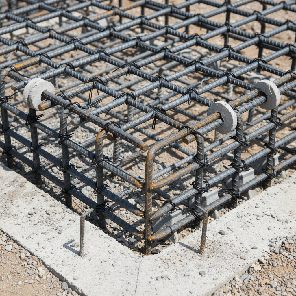
Use chairs, bolsters, spacers, and ties to hold the cage during concrete placement. Check cover, bar marks, spacing, laps, dowels, elevations, openings, and cleanliness. Photograph or record resolved issues where the project’s quality system requires evidence, then obtain the required inspection or approval before the pour.
For footing-specific layouts, the concrete footing rebar detail guide provides a narrower companion topic on footing reinforcement and coordination.
Which Reinforcement Materials Are Used?
Material selection follows the design, exposure, durability requirements, constructability, and approved specifications. Common options include carbon-steel reinforcing bars, epoxy-coated bars, glass-fibre-reinforced polymer bars, and welded wire mesh.
Metric reinforcing bars
10M, 15M, and 20M bars are common metric sizes, but their use is not determined by size alone. A 10M bar may appear in lighter foundation-wall or slab reinforcement, while 15M or 20M bars may be selected for higher demand or to reduce the number of bars in a congested area. The engineer’s schedule controls.
When comparing sizes, check clear spacing, minimum bend diameter, concrete flow, lap or development requirements, available stock, handling weight, and the placing crew’s ability to tie the cage accurately. Dass Rebar’s 10M rebar guide gives additional product-oriented context without replacing the project drawings.
Welded wire mesh
Welded wire mesh can support uniform reinforcement distribution in slabs-on-ground and other applications where it is specified. Standard configurations supplied by Dass Rebar include 6-inch by 6-inch mesh at 6/6, 9/9, and 10/10 gauges. Confirm sheet orientation, laps, support, elevation, and edge details before placement.
Mesh should be supported at the specified position; dragging it up after concrete placement does not reliably achieve the intended elevation. The wire-mesh overview compares common configurations and placement considerations.
Epoxy-coated steel and GFRB
Epoxy-coated reinforcement may be specified where corrosion risk is elevated, including some chloride-exposed conditions. It must be handled, stored, cut, bent, and repaired in accordance with the approved requirements so the coating is not unnecessarily damaged.
Glass Fibre Reinforcing Bars, or GFRB, are non-metallic reinforcement products with different structural, handling, cutting, development, and splice characteristics from steel. They are not a drop-in substitution. Confirm the design basis, approved product, detailing rules, and manufacturer requirements before changing material.
For planning only, Dass Rebar’s epoxy-coated rebar guidance discusses factors that affect coated-rebar decisions. It does not establish a project price or approve a material substitution.
| Option | Typical decision question | Detailing check |
|---|---|---|
| Black reinforcing steel | Is standard steel appropriate for the specified exposure? | Confirm grade, size, spacing, cover, bends, laps, and anchorage. |
| Epoxy-coated steel | Does the specification require added corrosion protection? | Coordinate coating, handling, damage repair, supports, and splice rules. |
| GFRB | Has the engineer approved a non-metallic reinforcement system? | Use the approved product’s design and development requirements. |
| Welded wire mesh | Is distributed slab reinforcement specified? | Check sheet designation, support, overlap, edges, and elevation. |
Product and supply coordination may also involve Dass Metal’s rebar product overview. The product source does not replace the structural specification or the approved submittal.
Foundation Rebar Detail: Field Quality-Control Checklist
A short, repeatable inspection sequence catches errors while they are still inexpensive to correct. Use the approved drawings and project inspection requirements as the checklist authority, then adapt the following prompts to the member being poured.
Before steel is placed
- Confirm the latest drawing revision is available to the detailer, foreman, inspector, and placing crew.
- Verify excavation, formwork, mud slab, waterproofing, embeds, and construction joints are ready for reinforcement.
- Separate bundles by pour and compare tags with the bar list.
- Check that bars, mesh, coating, grade, and accessories match the approved submittal.
After placement and before concrete
- Measure bar size, spacing, quantity, orientation, layer, and elevation against the detail.
- Check concrete cover at earth faces, formed faces, corners, steps, and penetrations using suitable spacers or chairs.
- Verify laps, hooks, dowels, development, couplers, corner returns, and continuity bars.
- Confirm reinforcement does not obstruct sleeves, embeds, anchor bolts, waterstops, or concrete access.
- Make sure the cage is tied and braced well enough to remain stable during placement and vibration.
- Remove mud, standing water, excessive oil, loose scale, debris, and other conditions that conflict with the specification.
Common problems to resolve early
Insufficient cover often results from missing chairs, unstable supports, or reinforcement placed directly on soil. Incorrect laps may result from applying a typical length without checking the approved design. Congestion can make concrete placement and vibration difficult. Each issue should be referred to the responsible design or project authority rather than solved by an unauthorized field change.
For broader construction coordination, the structural steel framing guide and steel bracing guide discuss related sequencing and load-path concepts. They are supplementary reading, not reinforcement design references.

Decisions That Improve Constructability
Good detailing anticipates the site rather than treating fabrication and placement as separate activities. Ask how bundles will reach the work area, where the crew will stand, how concrete will flow, and when inspections will occur.
Sequence reinforcement around the pour plan
Break schedules into practical placement zones. A footing cage, wall starter package, or slab mesh delivery should be identifiable without opening every bundle. This reduces handling, limits mix-ups, and gives the foreman a useful way to confirm completeness before the crew starts tying.
Review congestion at interfaces
Pay particular attention where footings meet walls, walls meet grade beams, columns land on mats, and reinforcement surrounds openings. A section or enlarged detail may be more useful than another general plan note. If a bar cannot be placed with the required cover and clearance, stop and obtain an approved resolution before fabrication or concrete.
Coordinate supply and documentation
A supplier that can estimate, detail, fabricate, tag, deliver, and support assembly can reduce handoff gaps, but the project team still needs a clear approval path. Confirm who reviews drawings, who authorizes revisions, who checks deliveries, and who signs the pre-pour inspection.
Dass Rebar’s Ontario operations include in-house estimating and detailing, fabrication, project management, dedicated trucking, and reinforcement products for residential, commercial, and infrastructure work. Those capabilities support coordination; they do not transfer design responsibility from the project’s professional team.
Frequently Asked Questions
What is the difference between a rebar detail and a rebar takeoff?
A takeoff measures the required reinforcement by size, length, shape, and quantity. A rebar detail shows where and how that reinforcement is placed, including spacing, layers, cover, laps, hooks, dowels, and connections. Fabrication and field placement normally need both coordinated outputs.
Who approves a foundation rebar detail in Ontario?
The responsible project design professional or other authority identified by the contract approves structural reinforcement details and changes. A fabricator or detailer can identify conflicts and propose constructability options, but should not independently change the engineer’s required size, spacing, cover, lap, or anchorage.
Are typical cover and lap numbers enough for a foundation?
No. Cover and development or splice requirements depend on the design, exposure, concrete, bar type, member, construction condition, and applicable standard. Treat typical values as coordination prompts only; use the approved drawings and specifications for the project requirement.
Can GFRB replace steel rebar in an existing detail?
Not without an approved redesign or substitution review. GFRB has different material properties, stiffness, handling requirements, development behaviour, and splice rules from steel. The engineer and project team must confirm that the selected product meets the intended structural and durability requirements.
Coordinate Your Next Foundation Rebar Detail
Start with the latest structural package, identify the governing Ontario requirements, and resolve cover, laps, corners, openings, congestion, and pour sequencing before fabrication. Then issue coordinated drawings, tag bundles by placement area, inspect the steel against the approved detail, and document any authorized changes.
For an Ontario project requiring estimating, rebar detailing, fabrication, delivery, or placement coordination, contact Dass Rebar with the drawing set, schedule, material requirements, and site constraints.