Foundation rebar detail is the precise layout, sizes, spacing, laps, and anchorage of reinforcing steel for footings, slabs, walls, and grade beams. For Ontario builds, Dass Rebar in 370 New Enterprise Way (Woodbridge) delivers in-house detailing, shop drawings, fabrication, and coordinated delivery so crews place the right steel with the right cover the first time.
By Navjot Dass — Dass Rebar
Last updated: 2026-04-26
Overview at a Glance
A foundation rebar detail shows exactly where each bar goes, its size (e.g., 10M, 15M), spacing, lap length, hooks, and cover. Clear details reduce site RFIs, speed inspections, and prevent cracking or settlement. This guide distills best practices for Ontario projects and shows how Dass Rebar turns drawings into ready-to-install steel.
Here’s what you’ll get from this complete guide (written for general contractors, concrete crews, and developers working across Ontario):
- Plain-language definitions of foundation reinforcement terms you’ll see on shop drawings
- Why accurate details matter for quality, safety, and schedule certainty
- A practical, step-by-step look at estimating → detailing → fabrication → delivery → assembly
- Quick tables for bar sizes, cover, laps, and wire mesh uses (6×6 6/6, 9/9, 10/10)
- Guidance on epoxy-coated steel and GFRP options for harsh exposure
- QC checklists you can hand to a foreman before first pour
Local considerations for 370 New Enterprise Way
- Freeze–thaw durability: Use proper concrete cover (often 2 in. or more on earth-formed footings) and consider epoxy-coated bars for chloride exposure.
- Seasonal coordination: Winter concreting needs rebar preheat protocols and reliable trucking windows; plan pour sequences to match daylight and temperature swings.
- MTO compliance: For municipal or highway-adjacent work, confirm Grade 400W/500W specs and documentation align with infrastructure submittal requirements.
What Is a Foundation Rebar Detail?
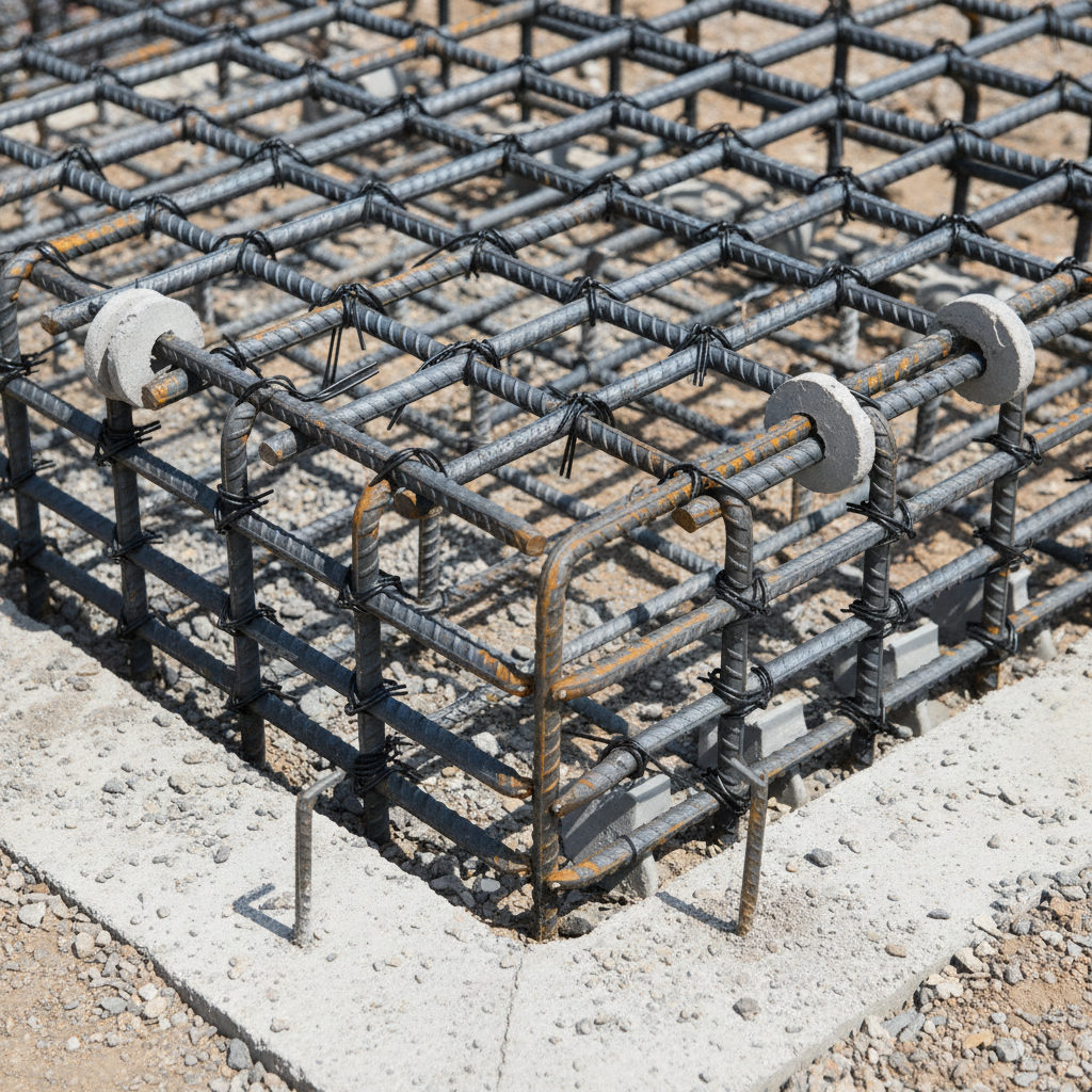
A foundation rebar detail is the set of shop drawings and schedules that define bar sizes, spacing, placement, laps, hooks, and cover for footings, slabs, walls, and grade beams. It translates structural intent into buildable instructions so fabrication and field crews install reinforcement correctly, consistently, and quickly.
Think of the foundation rebar detail as the instruction manual for your concrete’s internal skeleton. It shows:
- Member layouts: spread footings, strip footings, mat slabs, walls, piers, and grade beams
- Bar data: sizes (10M, 15M, 20M), counts, lengths, bends, hooks, and tags
- Spacing and stagger: typical 6 in.–18 in. on center ranges, with construction joint tying notes
- Cover requirements: often 2 in. at soil, 3 in. to forms facing earth, 1–2 in. at interior faces, per project specs
- Laps/splices: bar development typically 40d–60d unless otherwise specified
- Ties and stirrups: confinement around corners, columns, and openings
For crews, a good detail shortens setup time and reduces rework. For project managers, it de-risks inspections and compresses schedules. And for owners, it improves durability by controlling crack widths and load paths.
Why Foundation Rebar Details Matter
Accurate rebar details directly impact crack control, load transfer, and long-term durability. Clean drawings cut RFIs, reduce site waste, and help pass inspections. In our experience, precise detailing paired with punctual deliveries keeps pours on schedule and prevents costly cold-joint delays.
Here’s why this matters on every Ontario job:
- Quality: Correct bar size and spacing keep typical crack widths under control; tighter spacing at corners and openings limits stress concentrations.
- Safety and compliance: MTO-approved materials and traceable heat numbers support municipal and infrastructure audits.
- Schedule certainty: When tags, bundles, and bar lists match the pour sequence, crews average faster placement rates per hour.
- Cost discipline (without pricing): Right-sized bars and lap lengths reduce offcuts and minimize site bending.
- Longevity: Adequate cover (often 2–3 in. in exposed conditions) helps resist chloride ingress and freeze–thaw damage.
We often see the same pattern: unclear shop drawings lead to last‑minute field fixes, which extend forming cycles. With integrated estimating, detailing, fabrication, and delivery under one roof, coordination gaps drop and pour windows stay predictable.
How Foundation Rebar Detailing Works (Step-by-Step)
Effective rebar detailing flows from takeoff to shop drawings to fabrication, delivery, and assembly. The best results come from one coordinated provider handling estimating, detailing, bending, tagging, and trucking—so bar lists match pours, inspections move quickly, and crews install without guesswork.
Below is the field-tested flow our Ontario teams rely on to turn intent into install-ready steel:
- Preconstruction review: Confirm design criteria, exposure class, cover, lap class, and pour sequences with the GC and concrete lead.
- In-house estimating: Quantify 10M, 15M, and 20M runs; flag congestion zones early so bar sizes and spacing are constructible.
- Shop drawings & rebar detailing: Produce member-by-member details with tags, bends, hooks, stirrups, and dowel schedules. Include clear corner bars and continuity steel.
- Fabrication: Cut, bend, and bundle by pour break; pre-assemble cages where beneficial; label bundles for grid locations.
- Delivery logistics: Sequence the trucking fleet to your pour calendar; stage priority bundles nearest the placement zone.
- On-site assembly: Place chairs for cover, set grids, tie per schedule, verify laps (often 40d–60d), and brace for inspection.
- Inspection & pour: Walk down with checklists; correct minor issues (bar clearance, stagger) before concrete arrives.
For supply continuity and bar availability during fast-track schedules, see our rebar supply overview. If your foundation scope is footing-heavy, our footing rebar guide explains corner steel and dowel patterns in more depth.
Field-ready process table
| Phase | Your action | QC focus |
|---|---|---|
| Takeoff | Confirm 10M/15M/20M quantities | Identify congestion and lap zones |
| Detailing | Approve shop drawings with tags | Check cover, bends, and hooks |
| Fabrication | Bundle by pour sequence | Verify lengths and labels |
| Delivery | Stage near placement zones | Protect epoxy or GFRP |
| Assembly | Chair, tie, and brace | Measure laps (40d–60d) |
Types, Materials, and Approaches You’ll Specify
Foundation reinforcement typically blends black steel bars (Grade 400W/500W), welded wire mesh, and in some exposures epoxy-coated or GFRP bars. Choose bar size by loads and congestion, use mesh for slabs-on-ground, and upgrade coatings or composites where chlorides or non-magnetic needs apply.
Bar sizes and where they shine
- 10M rebar (≈ 11.3 mm / 0.45 in.): Common in slabs-on-ground, strip footings, and light walls; easy to place and tie. See our 10M rebar uses for typical patterns.
- 15M rebar (≈ 16 mm / 0.63 in.): Go-to for higher loads, grade beams, and shear-critical zones; fewer bars reduce congestion.
- 20M rebar (≈ 19.5 mm / 0.77 in.): For heavy footings or mats; coordinate bends and cover to maintain clearances at corners.
Mesh for speed and crack distribution
- Welded wire mesh 6×6 6/6: Light-duty slabs, walkways, and basement floors.
- Welded wire mesh 6×6 9/9: Mid-duty interior slabs; balances placement speed with performance.
- Welded wire mesh 6×6 10/10: Heavier slabs where uniform crack control is key.
For mesh selection, our overview of wire mesh types and benefits compares gauges and use cases.
Coatings and composites
- Epoxy-coated rebar: Ideal for chloride exposure (de-icing, splash zones). Handle carefully to avoid coating damage—pad slings and avoid dragging. See our epoxy rebar guidance for planning tips.
- GFRP (glass fiber–reinforced polymer) bars: Non-corroding, non-magnetic. Useful near electromagnetic equipment or where corrosion is a top risk.
Comparison snapshot
| Option | Best for | Placement notes |
|---|---|---|
| Grade 400W/500W (black steel) | General footings, slabs, walls | Standard cover (often 2–3 in.), lap 40d–60d |
| Epoxy-coated steel | De-icing or harsh exposure | Protect coating; use padded spacers |
| GFRP bars | Non-corrosive or non-magnetic needs | Different lap rules; align with specs |
| Welded wire mesh | Slabs-on-ground, crack distribution | Chair to mid-depth; tie overlaps per sheet |
For additional background on product lines, Dass Metal’s rebar overview outlines common stock forms and handling pointers that align with field realities.
Best Practices for Clean, Buildable Foundation Details
Prioritize clear corner bars, proper cover, realistic laps, and sequence-friendly tagging. In the field, chairs before steel, verify 40d–60d laps, stagger splices, protect epoxy, and measure top-of-steel elevations. Small checks upstream prevent cracked corners and inspection delays.
- Corner integrity: Add L-bars or hook bars to confine corners; increase density where load paths turn 90°.
- Concrete cover: Use chairs/spacers to hold 2–3 in. at earth faces and 1–2 in. at interior forms unless drawings specify otherwise.
- Lap splices and stagger: Keep laps clear of high-shear zones and stagger adjacent laps by at least 24 in. where possible.
- Dowels and continuity: Tie dowels firmly at joints; mark elevations so top-of-steel stays consistent before pour.
- Openings and penetrations: Add U-bars and trim steel around sleeves to maintain crack control.
- Inspection prep: Lay out a pre-pour checklist: cover, laps, bar tags, epoxy protection, and rebar chair spacing.
On real jobs, two numbers drive outcomes: cover and lap. If cover is short by even 0.5 in., durability drops fast in freeze–thaw cycles. And if laps fall short of 40d, bars won’t fully develop—raising the risk of shrinkage cracks telegraphing through slabs.

Tools, Checklists, and Resources
Use bar lists, bending schedules, tagged bundles, and pour-by-pour staging to speed placement. Field checklists for cover, laps, and elevations enable fast inspections. Quick references for 10M/15M/20M sizes and mesh gauges keep crews aligned without guesswork.
Templates you can use today
- Bar list sheet: Member, tag, size, length, bend, quantity, and bundle ID
- Pre-pour inspection checklist: Cover (2–3 in. exposed), laps (40d–60d), epoxy protection, bar tag match, elevation marks
- Pour sequence map: Color-coded plan showing bundle staging against staging zones
- Mesh overlap card: 6×6 6/6, 9/9, 10/10 sheet overlap distances and chair spacing notes
Reference links (practical context)
- Stock forms and handling in Dass Metal’s rebar overview for big-picture supply coordination
- See how steel framing ties into foundations in this framing guide with logistics lessons that carry into rebar staging
- Load path concepts echoed in this bracing guide help explain why corner confinement bars pay off
Mini Case Studies and Real-World Scenarios
Coordinated detailing, fabrication, and delivery cut RFIs, shorten inspections, and stabilize pour windows. When bundles arrive tagged to match drawings, crews place steel faster and inspectors sign off quicker—keeping forms cycling and schedules intact.
Toronto infill with dense footings
- Challenge: Congested corner dowels and limited laydown made placement slow.
- Approach: We tightened bar schedules, swapped select 10M runs for 15M to reduce bar count, and pre-assembled cage modules.
- Outcome: Placement time per footing dropped as modules landed with clear tags; inspection passed on first walk.
Waterloo mid-rise slab-on-ground
- Challenge: Large slab with multiple penetrations risked uneven crack distribution.
- Approach: Used 6×6 9/9 mesh with added U-bars at sleeves; mapped pour breaks to match bundles.
- Outcome: Even crack patterns within expected limits; crews advanced to walls without rework.
Durability near de-icing exposure
- Challenge: Chloride splash zones at grade beams along a busy access route.
- Approach: Specified epoxy-coated 15M with padded spacers; trained crew on coating protection.
- Outcome: Coating integrity verified at inspection; cover measured at 2.5–3.0 in. consistently.
If you’re aligning a new foundation package, our integrated approach—from stock supply to coated options to size selection—keeps drawings, tags, and deliveries synchronized.
Frequently Asked Questions
Most questions about foundation rebar details boil down to placement clarity, cover, laps, and material choice. Get these four right—supported by accurate shop drawings—and inspections move faster while cracks and callbacks drop.
What should a foundation rebar detail include?
Include bar sizes, spacing, lap lengths, hooks, and cover, plus member-by-member schedules, tags, and bend details. Clearly show corner bars, dowels, and openings. A good detail also groups bars by pour sequence so fabrication and delivery can be staged for faster placement.
When do I use 10M vs. 15M rebar?
Use 10M for lighter loads, thinner slabs, and tight ties. Choose 15M where higher loads or fewer bars will ease congestion, such as grade beams or heavy strip footings. Always follow the structural drawings, and confirm clearances at corners and penetrations.
How much concrete cover do I need at foundations?
Project specs govern, but common targets are around 2 in. over bars cast against soil and 1–2 in. at interior faces or formed surfaces. In harsher exposures, more cover and epoxy-coated steel improve durability. Always verify with your engineer of record.
Do epoxy-coated or GFRP bars change lap lengths?
They can. Coatings and composites often have different development and splice requirements than black steel. Follow the project specifications and manufacturer data, and coordinate early so detailing and field laps align with the approved standard.
Key Takeaways
Clarity wins. Pair accurate foundation rebar details with staged delivery, consistent cover, and realistic laps. That triad shortens inspections, reduces rework, and keeps pours on time across Ontario projects.
- Foundation rebar detail turns structural intent into buildable instructions
- Cover (often 2–3 in.) and laps (commonly 40d–60d) drive durability
- Stage bundles by pour to raise placement rates and speed inspections
- Use epoxy or GFRP where chloride or non-magnetic needs apply
- Leverage one provider for estimating → detailing → fabrication → trucking
Next Steps
Align scope early: confirm bar sizes, cover, laps, and pour sequences. Then lock shop drawings, tag bundles by phase, and schedule trucks to your calendar. One coordinated provider keeps drawings, fabrication, and delivery in sync.
Ready to align your package? Explore Ontario-wide rebar supply and logistics, dig into 10M size selection, and review epoxy-coated practices. Book a discovery session with our team in 370 New Enterprise Way (Woodbridge) to keep your next pour on schedule.