Tekla rebar detailing is the 3D modeling, scheduling, and documentation of reinforcing steel in Tekla Structures. It produces constructible models, bar lists, and shop drawings that cut clashes and rework. For Woodbridge builders, Tekla-based workflows align takeoffs with fabrication and delivery windows so pours stay on schedule.
By Navjot Dass • Last updated: 2026-07-04
Overview and table of contents
This complete guide explains Tekla rebar detailing—from core definitions to field-ready outputs. Use it to brief stakeholders, standardize rules, and connect estimating, fabrication, delivery, and assembly. We include checklists, examples, and QA points Ontario teams can apply immediately.
Here’s what you’ll learn in this guide:
- What Tekla rebar detailing is and how it compares to 2D approaches
- Why model-driven reinforcement matters for Ontario projects
- How the end-to-end workflow runs—intake to field revision
- Detailing methods, lap/anchorage rules, and cover by element type
- Best practices our in-house team uses on active jobs
- Tools, standards, and resources to keep submittals moving
- Mini case studies with 10M, 15M, and 20M examples
What is Tekla rebar detailing?
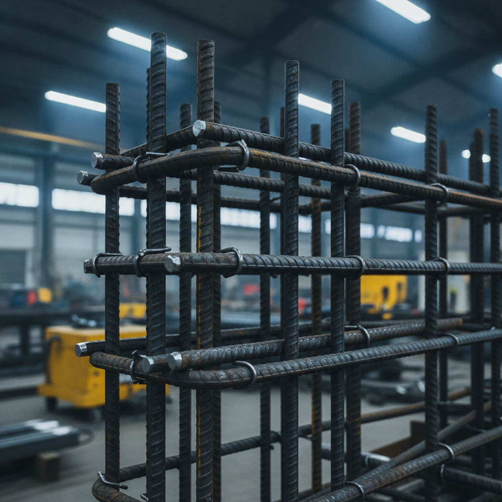
Tekla rebar detailing is the creation of a constructible 3D reinforcement model with linked shop drawings and bending schedules. The model drives accurate bar counts and lengths, reduces clashes, and outputs shop-ready data that maps cleanly to fabrication and delivery sequencing.
At Dass Rebar, detailing is integrated with estimating, fabrication, project management, delivery, and on-site assembly. That closed loop improves accuracy from the first takeoff to the final inspection. We routinely package:
- Placement drawings by element (slabs, walls, cores, beams, columns, mats, stairs)
- Bending schedules and bar lists grouped by 10M, 15M, and 20M
- Callouts for hooks, laps, and couplers with clear view orientations
- Export files that sync with shop cutting and bending limits
Level of Detail typically lands around LOD 350–400 for reinforcement objects (primary bars, ties, stirrups, links, and couplers). Cover guidance often follows 40 mm (≈1.5 in) for slabs, 50 mm (≈2 in) for interior walls, and 75 mm (≈3 in) at soil-facing faces, with laps commonly 40–60 bar diameters depending on code class and bar size.
Why Tekla rebar detailing matters
3D reinforcement modeling improves takeoff accuracy, reduces RFIs, and keeps pours on track. With linked bar lists and drawings, teams stage deliveries by pour, cut field cutting, and speed inspections—especially in dense cores and congested slab zones.
Here’s the thing: rebar is unforgiving. A misplaced 15M lap or a missed coupler can ripple into hours of delay. Tekla-based detail reduces that risk by making laps, hooks, and cover visible early—long before a truck shows up. In our experience across Ontario projects, model-driven takeoffs align with final usage within a tight variance when solid QA is enforced.
- Clash reduction: Hard/soft checks against embeds, sleeves, PT ducts, and conduits
- Procurement clarity: Bar lists auto-grouped by diameter, length, and shape (Grade 400W/500W)
- Schedule discipline: Sequencing by pour break, level, and crane zone to cut handling moves
- Compliance: MTO-approved processes help infrastructure submittals and inspections move faster
For builders around Woodbridge, tighter staging matters. A truck that arrives pre-sorted to the crane’s reach can save dozens of handling moves per ton, which is often the difference between a smooth pour and a hold-up.
How Tekla rebar detailing works (end-to-end)
A successful detailing cycle starts with design intake and model setup, proceeds through rebar layout and rule checks, and ends with shop outputs, logistics planning, and field-ready revisions. Each step has a defined QA gate to keep models, lists, and trucks in sync.
- Design intake – Gather IFC/Revit, structural sheets, and rebar notes; confirm cover, laps, hooks, and coupler requirements.
- Model setup – Lock grids/levels, define element classes, load bar catalogs (10M–20M), and standardize naming.
- Layout – Place primary bars, distribution steel, ties, stirrups, hooks, and mechanical couplers; set spacing (e.g., 150–200 mm on center) by rule.
- QA checks – Verify cover, splice lengths, congestion hotspots, and constructability; flag openings and sleeve banks for review.
- Shop outputs – Generate placement views, bending schedules, and bar lists grouped by pour sequence.
- Fabrication link – Export cut/bend data aligned to shop machine capacities; avoid compound bends on heavy 20M.
- Logistics – Split deliveries by pour and crane zone; pre-tag bundles to reduce searching on deck.
- Field support – Issue revisions with clear deltas; maintain a stable bar mark system to prevent resorting.
Looking for a deeper primer before you kick off a model? Our introductory explainer on foundations of 3D reinforcement is a helpful warm-up in the 3D rebar detailing guide. If you prefer a plain-English overview of terminology, our rebar detailing basics article is a quick read for new team members.
Coordination with estimating
When detailing starts from clean assumptions, takeoffs become more dependable. We align estimating units with model outputs (bar length, count, and weight) so procurement can issue POs without rework. Typical modeling conventions include fixed bar shapes for repetitive elements, predictable lap zones, and shape codes synced to shop machines.
- Use standard shapes for slabs and walls to keep schedules stable if geometry shifts.
- Confirm lap zones every 20–30 feet along walls to avoid planes of weakness.
- Group counts by element and pour so buyers can order and stage intelligently.
Fabrication handoff
Cutting and bending constraints define what’s buildable. We check minimum bend diameters, overall lengths, and hook geometry against shop limits before issuing. For 20M, compound bends are discouraged; we often split into two shapes with a tie overlap at corners to maintain field efficiency.
- Validate minimum bend diameters for 10M, 15M, and 20M per shop rules.
- Pre-sequence bundles by crane zone to reduce handling steps at placement.
- Include clear callouts for epoxy-coated bars where durability is specified.
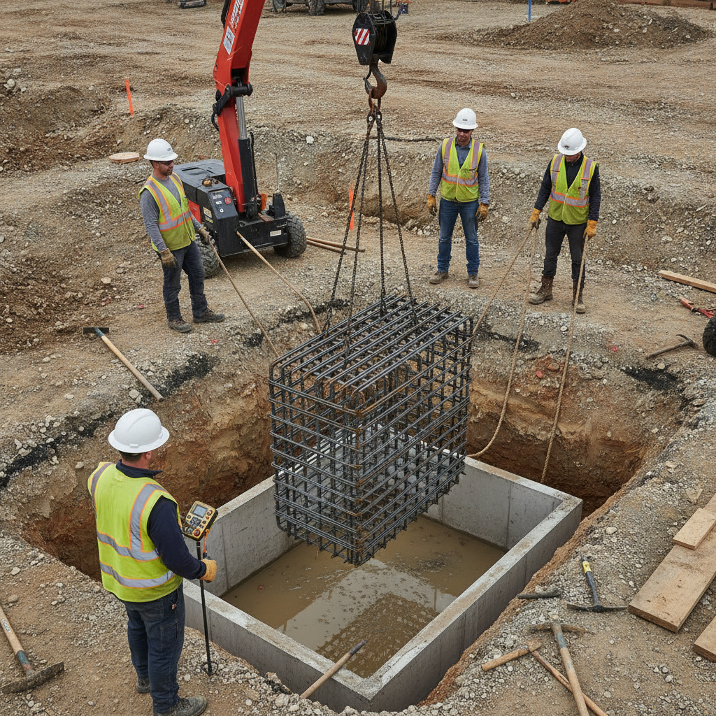
Logistics and delivery
Trucking is where models win or lose time. We stage by pour, level, and crane reach, which helps crews tie more steel with fewer lifts. Pre-tagging bundles to the drawing’s zone IDs cuts search time and speeds inspections.
- Deliver by pour break; avoid mixing levels to prevent sorting on deck.
- Align truck arrival windows with inspection slots and pour timing.
- Use weather-protected laydown for epoxy-coated or GFRB items.
For more on how we translate drawings into shop and field action, see our practical breakdown in rebar shop drawings and our process tour in rebar fabrication guidance.
Types, methods, and detailing approaches
Tekla supports element-based rebar sets, reusable library parts, and parametric custom components. Mixing these methods balances speed and control so marks remain stable through revisions and bar lists keep mapping cleanly to fabrication and trucks.
Element-driven reinforcement
Attach rebar sets to slabs, walls, and beams so bars auto-adjust if geometry changes. Drive spacing with rules (e.g., 200 mm typical; tighten to 150 mm near openings) and maintain cover by element class. Associativity protects your schedule if the structural model evolves.
- Use object-associated sets for walls and slabs with predictable distribution steel.
- Set cover profiles per element (40 mm slabs, 50 mm interior walls, 75 mm soil-facing).
- Flag sleeve clusters and shear studs for congestion checks before issuance.
Template and library parts
Standard details speed delivery without sacrificing clarity. Save cages for pile caps, typical columns, and stair flights with predefined hooks and laps. Keep the shape code catalog synchronized with fabrication so bar marks don’t shuffle after revisions.
- Maintain a library of column cages with stirrup spacing options.
- Reuse shear link families across projects for consistent schedules.
- Version-control templates so field crews see consistent callouts job-to-job.
Parametric custom components
Complex joints and retrofits benefit from parametric parts. Use custom components for beam-column joints with variable depths and anchorage, or where lap splices are impractical and couplers are required. Automated naming (Level–Element–Zone–Mark–Dia) prevents resorting when details change late.
- Switch to mechanical couplers where lap length or congestion prevents splicing.
- Automate naming and sorting so mark sequences hold through revisions.
- Test bendability for larger diameters in corners and tight radii before issuance.
| Approach | Speed | Control | Best for |
|---|---|---|---|
| Element-driven sets | High | Medium | Slabs, walls, typical beams |
| Template/library | Very high | Medium | Pile caps, repeating columns |
| Parametric custom | Medium | High | Irregular joints, retrofits |
Want a broader context for how reinforcement choices influence performance? Our big-picture primer on material options in the reinforcing steel complete guide is a helpful companion read.
Best practices our detailers follow
Document rules early, model for constructability, and validate with disciplined QA. Keep naming stable, stagger laps, and coordinate with fabrication so every mark maps to a bend and a truck slot—with drawings legible at arm’s length.
Rules-first detailing
Before anyone lays a bar, we lock standards: Grade 400W/500W usage, cover, splice classes, hooks, coupler families, and welded wire mesh options (6″×6″ at 6/6, 9/9, or 10/10). These decisions eliminate ambiguity in congested zones and speed approvals.
- Publish a one-page standard per project with laps by bar size (e.g., 40–60ϕ).
- Define epoxy-coated use cases: exposure, de-icing, or infrastructure durability.
- Confirm shear and temperature steel strategies early on slabs and walls.
Buildability and field clarity
Detractors of 3D sometimes worry that drawings get busy. We counter that with view discipline: callouts large enough to read, north oriented to site grids, and legible at arm’s length. Complex corners get a blown-up detail and a note that matches the shop’s capacity.
- Avoid compound bends on 20M; split into two shapes with a tie overlap if needed.
- Place lap zones away from openings and stress concentrations.
- Use couplers where lap space is limited or congestion is high.
Change control
Revisions happen. We keep them clean with clouding, delta tags, and issue logs by pour. Stable bar marks are non-negotiable; naming conventions prevent resorting and protect procurement, shop, and field sequences.
- Map each delta to a pour and level to control risk.
- Re-run coverage and splice checks after each design update.
- Document impacts on shop and trucking to keep the critical path intact.
Tools, standards, and resources
Pair Tekla Structures with a synchronized shape catalog, Ontario-ready submittal standards, and recognized North American guidance for cover, laps, and hooks. Keep everything versioned so approvals and inspections move without friction.
For reinforcing teams who also coordinate with structural steel, this overview of structural framing systems across the JDASS network provides useful context on interfaces and erection constraints. For a broader framing perspective, see this structural steel framing guide that many Ontario GCs share during precon to align trades around staging limits and crane picks.
If you want a quick tour of how our cut-and-bend work ties into detailing deliverables, our process page on rebar fabrication outlines the practical constraints we design to—minimum bend diameters, bar length limits, and tagging methods that speed placement.
Case studies and practical examples
On recent Ontario projects, model-based detailing shortened submittal cycles and tightened field fit. By sequencing bars to pours and standardizing marks, crews tied faster and inspections cleared with fewer RFIs—even in congested cores.
High-rise core: 15M around sleeve banks
Challenge: Vertical 15M conflicted with elevator sleeve banks at a downtown core. Action: Switched select laps to couplers; shifted spacing to maintain 50 mm cover; reoriented drawings to match grid. Result: Eliminated on-site cutting and held the pour window.
- Used associativity so bars adjusted when sleeve locations shifted.
- Applied couplers to alternate bars to break splice planes.
- Grouped deliveries by crane zone to reduce handling by dozens of moves per ton.
Mat footing: 20M top and bottom mats
Challenge: Corner geometry risked unbendable shapes for 20M. Action: Split bends into two pieces with a tie overlap; enforced shop radius limits; tagged bundles by zone. Result: Smoother tying sequence and faster inspection sign-offs.
- Pre-checked bendability and maximum stock lengths at the shop.
- Kept lap zones staggered to avoid planes of weakness.
- Delivered per pour break to keep deck clean and organized.
Stair flights: 10M distribution steel
Challenge: Mixed orientations slowed crew interpretation. Action: Aligned plan/section views to site north; enlarged callouts and added a legible legend. Result: Crews placed faster and inspectors cleared quicker.
- Saved a stair cage template with predefined hooks and laps for reuse.
- Standardized mark naming to prevent re-sorting after late changes.
- Issued a one-page field checklist for quick compliance checks.
Local considerations for Woodbridge
- Plan truck arrivals to avoid congestion near Queen St / Highway 50 during peak traffic windows.
- Winter pours demand tighter sequencing; protect bar stock, laps, and couplers against freeze-thaw exposure.
- Coordinate laydown near Fogal Rd / Highway 50 when crane swing is limited on compact sites.
Frequently asked questions (FAQ)
These concise answers cover modeling scope, deliverables, accuracy, and how revisions are controlled—so you can evaluate whether Tekla-based detailing aligns with your schedule, shop, and field needs.
What does Tekla rebar detailing include?
It includes 3D reinforcement modeling, placement drawings, bending schedules, and bar lists aligned to fabrication. QA covers cover checks, splice lengths, congestion, and coordination with embeds, sleeves, and PT ducts as required by design.
How do you handle revisions and RFIs?
We maintain revision logs, cloud deltas on drawing sheets, and stable bar marks. After each design update, we re-run cover and splice checks, regenerate affected lists, and coordinate with fabrication and trucking so pours keep their time slots.
Can Tekla detailing improve takeoff accuracy?
Yes. Model-driven takeoffs produce bar counts and lengths directly from the 3D model, which reduces manual errors. With disciplined QA, we see close alignment between modeled quantities and final field use across slabs, walls, beams, and columns.
Which bar sizes do you commonly model?
In Ontario, 10M, 15M, and 20M bars are common. We also model welded wire mesh for slabs when specified, and epoxy-coated rebar where durability or exposure conditions warrant additional protection.
Conclusion and next steps
When Tekla rebar detailing drives procurement, fabrication, and staging, crews tie faster and pours hold. The most effective first step is a scoped review of drawings, standards, and sequencing with an integrated detailing-fabrication partner.
Key takeaways:
- Standardize cover, laps, hooks, and coupler use before modeling.
- Keep bar marks stable; sort by level, element, zone, and diameter.
- Sequence deliveries by pour and crane zone to cut handling.
- Design to shop limits—especially bend radii and lengths for 20M.
- Use couplers where splicing space is tight or congestion is high.
Next steps:
- Share IFC/Revit and structural sheets for a quick scope review.
- Agree on a one-page project standard (cover, laps, hooks, mesh, epoxy).
- Define pour breaks and crane zones to drive bundling and delivery.
Explore more fundamentals and options in our reinforcing bar guide and this plain-language overview of rebar detailing. If you’re mapping out manpower and staging, our step-by-step rebar estimating guide aligns modeling with procurement and delivery planning.