
Rebar detailing in Revit is the practice of modeling concrete reinforcement so the output becomes constructible shop data—bar marks, cut lists, bend shapes, covers, and placing drawings. In Woodbridge and across Ontario, aligning that model to stocked sizes and grades lets Dass Rebar fabricate, deliver, and support on-site assembly with fewer RFIs and field fixes.
By Navjot Dass • Last updated: 2026-07-11
Overview
Rebar detailing in Revit pays off when digital decisions match shop reality. Lock bar sizes, grades, covers, splice rules, and bend shapes to your fabricator’s standards. That alignment turns BIM into accurate shop drawings, predictable deliveries, and faster placement with fewer change orders on Ontario jobs.
As an Ontario supplier and fabricator (in business since 1986), we turn models into bundled, labeled deliveries daily. Our in-house estimating, detailing, fabrication, delivery, and on-site assembly teams keep residential, commercial, and infrastructure projects moving. For background, skim our rebar detailing basics and Ontario fabrication guide.
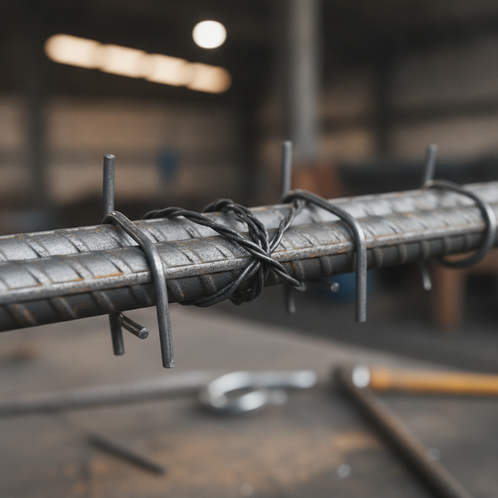
What Rebar Detailing in Revit Actually Produces (and Who Uses It)
A well-detailed Revit model outputs shop drawings, bar lists, bending schedules, and placing drawings. Fabricators cut and bend from it; site crews place and tie; project managers schedule pours and inspections. Matching stocked sizes (10m, 15m, 20m) and grades (400W/500W) keeps the flow smooth.
In practice, your model generates:
- Bar schedules and marks that drive cutting, labeling, and field tracking.
- Standard bend shapes mapped to our shop libraries for consistent results.
- Cut lists tied to stock and bend allowances so bundles arrive optimized.
- Placing drawings with clear elevations/sections crews can follow confidently.
- Cover/splice data that inspectors can verify against structural notes.
Who uses these outputs?
- Detailers/fabricators convert marks to cut-and-bend instructions.
- Site crews place by mark and sheet, reducing guesswork.
- PMs/supers line up deliveries, pours, and inspections.
If you’re new to packaging, see our explainer on rebar shop drawings.
Step-by-Step: Rebar Detailing Workflow in Revit for Fabrication-Ready Output
Start from verified specs, then model to stocked sizes and mapped bend shapes. Generate unambiguous marks and schedules, and run a pre-fabrication review with your supplier. That sequence prevents cutting the wrong grade, coating, or length.
- Confirm specs: Verify grade (400W/500W), epoxy needs, covers, and lap rules from the structural set.
- Align sizes: Model with stocked sizes (10m, 15m, 20m) and any GFRB or mesh substitutions allowed.
- Use mapped shapes: Choose bending shapes we support; avoid custom one-offs unless the EOR approves.
- Control splices: Place laps where crews can tie safely and efficiently; avoid congested nodes.
- QA schedules: Check marks, lengths, quantities, and shape codes for ambiguity.
- Issue shop set: Publish placing drawings with clear callouts, sections, and notes.
- Pre-fab review: Walk the model with our detailing team before anything is cut.
We pair this flow with detailing coordination so your Revit set becomes a reliable fabrication plan.
Where Revit Models Break Down at the Fabrication Stage
Models fail when assumptions don’t match shop or site reality—nonstandard bends, unavailable sizes, unclear covers, or splice locations that can’t be placed. Fixing those before cutting avoids scrap, delivery delays, and pour resequencing.
- Custom shapes: We decline nonstandard shapes without EOR sign-off. They add days of back-and-forth and don’t save time on site.
- Unavailable sizes/grades: Modeling 25m when 20m is stocked triggers lead-time issues and substitutions.
- Vague cover/splice: If cover is ambiguous, we halt cutting and raise an RFI—pour delays cost more than a quick clarification.
- Coating mismatches: Corrosion-prone zones need epoxy-coated bar or GFRB; the model must flag those areas clearly.
- Mesh vs. bar: Slabs that could be mesh but are modeled with bars slow placement and add tying time.
We keep Revit decisions inside the guardrails used in our constructability reviews so shop and field stay aligned.
How Detailing Decisions Affect Your Cut List, Bending Schedule, and Delivery
Every modeling choice shows up in your cut list and on the truck. Standard shapes, stocked sizes, and workable splices cut shop time and land bundles in the right order for your pour sequence.
| Detailing decision | Fabrication impact | Delivery/field impact |
|---|---|---|
| Use stocked sizes (10m/15m/20m) | Faster cutting; fewer partials | Predictable drops per pour |
| Map to standard bend shapes | Automated bending; fewer rejects | Bundles labeled by mark |
| Place workable lap splices | Optimized lengths; less waste | Quicker tying; fewer clashes |
| Specify epoxy/GFRB zones | Correct coating at cut/bend | Inspection-ready by area |
| Swap slab bars for mesh where allowed | Shorter fab window | Faster placement |
Case example: six-story podium slab in Vaughan
- Grades by element: We recommend 500W in shear walls/cores for strength efficiency and 400W in flat slabs to simplify handling and tying.
- Sizes by function: 15m rebar for top/bottom mats in typical bays; 20m at column strips and around openings. See our quick size context in reinforcing steel sizes.
- Mesh in parking bays: Where the EOR allows, 6″×6″ 6/6 welded wire mesh replaces individual bars. In Revit, model with fabric sheets so schedules and placing drawings stay accurate.
- Edge exposure: At slab edges facing de-icing spray, we prefer GFRB or epoxy-coated steel. GFRB resists corrosion but has different bend limits—don’t model tight hooks that can’t be fabricated.
- Sequenced deliveries: We bundle by level and drop zones so the crane sets steel close to the pour line, not a distant laydown.
Opinion, learned the hard way: if your model mixes 400W and 500W without clear tags, mark collisions are inevitable. We won’t cut until grades are explicit per element—one afternoon of cleanup beats a delayed pour.
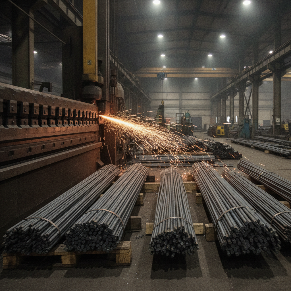
Working With a Detailer Who Also Fabricates and Supplies
One accountable partner reduces rework. With estimating, detailing, fabrication, delivery, and on-site assembly in-house, Dass Rebar turns your Revit set into bundled, labeled bar deliveries matched to your pour sequence—saving crane time and site labor.
- In-house estimating/detailing aligns early with the engineer’s notes.
- Cutting and bending runs on libraries that mirror standard Revit shapes.
- Dedicated trucking fleet times drops to your pour plan across the GTA.
- MTO-approved supply with Grade 400W/500W, epoxy-coated options, GFRB, and welded wire mesh.
- On-site assembly support so crews place by mark and bundle.
Need a pre-fabrication model check? Share your Revit set and pour schedule. We’ll validate sizes (10m/15m/20m), grades (400W/500W), coatings, and splice strategy before cutting—so delivery aligns to your site plan.
Local Tip: Coordinating Revit Detailing With Your Rebar Supplier
In Woodbridge, lock grade callouts, bar sizes, and pour sequencing with a local fabricator early. We stage drops to miss congestion near Queen Street and Highway 50 and bundle by level so crews start tying the moment trucks arrive.
Working from Woodbridge, we align BIM data to what’s in stock and how crews place steel on real sites. Share drawings by level/pour and we’ll bundle by mark to match sequence. Two practical notes below save time week after week.
Local considerations for Woodbridge
- Schedule early-morning deliveries to avoid peak backups at Queen St / Highway 50.
- For industrial sites, we time arrivals near Fogal Rd / Highway 50 so bundles land close to the pour line.
- For infrastructure scopes, confirm MTO-approved 400W/500W callouts in the model; inspectors move faster when grades are explicit.
Insider logistics tip for Woodbridge crews
Bundle heavy marks closest to the first pour area and request staggered arrivals. Our trucking team coordinates with your site lead so cranes pick straight from the truck—less double-handling, fewer delays.
Frequently Asked Questions
Most questions focus on mapping a Revit model to shop reality—sizes, grades, coatings, splices, and delivery sequencing. Here are concise answers we give GCs and concrete contractors across Ontario.
How do I make my Revit rebar schedules fabricator-ready?
Use stocked sizes (10m, 15m, 20m), mapped bend shapes, and clear cover/splice notes. Include bar marks, lengths, and shape codes. Then have your fabricator review the set against their bending library before you issue for construction.
When should I model welded wire mesh instead of bars?
Follow the engineer’s spec. Where permitted—like typical parking bays—6″×6″ 6/6, 9/9, or 10/10 mesh speeds placement. In Revit, use fabric sheets so schedules and placing drawings match the field approach.
GFRB or epoxy-coated steel—what’s your stance?
For edges and decks exposed to de-icing spray, we favor GFRB for corrosion resistance. Epoxy-coated steel is a good option but coatings can be damaged at bends and handling. GFRB needs looser bends—don’t model tight hooks you can’t build.
Is rebar detailing in Revit worthwhile on small jobs?
For modest residential pours, clear 2D shop drawings plus a precise bar list may be enough. For multi-level or complex slabs/walls, Revit pays for itself by preventing clashes and aligning deliveries with your pour sequence.
Key Takeaways
- Model to real stock (10m/15m/20m) and grades (400W/500W) so schedules flow to cutting without substitutions.
- We reject custom bend shapes without EOR approval—lost days beat any theoretical savings.
- Use mesh and GFRB intentionally; they change both the fabrication window and the placing drawings.
- Local coordination in Woodbridge means staging around Highway 50 traffic and bundling by pour zone.
For cross-trade context that often overlaps reinforcement sequencing, explore structural topics like framing systems, recent industry event highlights, and broader updates tagged under Dass Rebar news.