Welded wire mesh reinforcement is a factory-welded grid of steel wires used to control cracking and distribute loads in concrete. It arrives in sheets or rolls, installs quickly, and improves slab and wall performance. For Woodbridge, ON projects, Dass Rebar supplies standard 6×6 6/6, 6×6 9/9, and 6×6 10/10 mesh with in-house detailing and coordinated delivery.
By Navjot Dass • Last updated: 2026-05-18
Quick Summary
Welded wire mesh reinforcement (WWR) is a prefabricated steel grid that speeds placement, limits shrinkage and temperature crack widths, and improves load distribution in slabs, walls, and pavements. Match wire size, spacing, and coating to the engineer’s design. Dass Rebar stocks common 6×6 meshes and provides shop drawings and scheduled deliveries across Ontario.
This complete guide is built for general contractors, concrete contractors, developers, and construction managers across Ontario who need reliable, practical answers—fast.
- What WWR is, how it works, and why it matters
- How WWR compares with conventional rebar mats
- Specs that count: spacing, wire size, panel formats, coatings
- Step-by-step installation and QA/QC checklists
- Local tips for Woodbridge and the broader GTA
Table of contents
- What Is WWR?
- Why WWR Matters
- How WWR Works
- Types and Specs
- WWR vs. Rebar
- Best Practices & Installation
- Tools and Resources
- Quality Control & Inspection
- Case Studies & Examples
- Common Mistakes
- Coordinating with Dass Rebar
- FAQ
- Conclusion & Next Steps
Local considerations for Woodbridge and the GTA
- Plan around freeze–thaw cycles typical in Southern Ontario; protect early-age concrete and maintain curing to limit plastic-shrinkage cracking.
- Stage deliveries to avoid peak GTA traffic windows; Dass Rebar’s dedicated trucking fleet helps sequence mesh near multiple pours in a single day.
- For municipal and infrastructure scopes, align submittals with local specifications and the engineer of record; our MTO-approved status supports compliance.
What Is Welded Wire Mesh Reinforcement?
Welded wire mesh reinforcement (WWR) is a two-way grid of steel wires welded at every intersection to act as crack-control and light structural reinforcement in concrete. Delivered as flat panels or rolls, it installs faster than tying loose bars and offers uniform spacing for predictable performance and easier inspection.
At its core, WWR is purpose-built for speed, consistency, and dependable crack control. Each intersection is resistance-welded at the mill, creating a rigid mat with reliable geometry. In slab-on-grade and pavement applications, the grid sits near the tension zone to restrain microcracks as they form, helping maintain tight crack widths and serviceable surfaces.
- Common spacings: 6 in x 6 in for slabs, sidewalks, toppings, and aprons; other patterns exist per design.
- Typical wire sizes: 6/6, 9/9, 10/10 gauges in Canadian practice (often aligned with W-number notation in U.S. specs).
- Formats: Flat panels for precise lap control; rolls for speed on long corridors and light-duty pavements.
- Use cases: Slab-on-grade, metal deck composites, CMU wall bed joints, sidewalks, aprons, drive lanes, and light foundations.
Self-contained answer: WWR is a pre-welded steel grid placed near the concrete tension face to limit shrinkage and temperature crack widths and to share imposed loads. It arrives ready to place, commonly in 6×6 spacing and selected wire gauges, reducing on-site labor compared with tying individual bars.
Why Welded Wire Mesh Reinforcement Matters
WWR matters because it transforms a few wide cracks into many tight ones, which improves long-term serviceability and appearance. Factory-welded spacing accelerates installation and simplifies inspection, helping Ontario contractors keep aggressive schedules while limiting callbacks related to early-age or seasonal cracking.
Concrete shrinks as it cures and moves with temperature. Without well-distributed steel, cracks open wider and concentrate stress. WWR intercepts microcracks at regular intervals. Numerous small wires engage together, helping slabs carry traffic with fewer finish defects and more uniform joint performance.
- Serviceability: Tighter crack widths improve ride quality, reduce moisture ingress, and protect finishes.
- Speed: Crews place broad panels quickly—often minutes per bay—requiring fewer ties and checks than rebar mats.
- Consistency: Mill-welded intersections maintain geometry, so inspectors can verify spacing at a glance.
- Coordination: Dass Rebar stocks 6×6 6/6, 9/9, and 10/10 meshes to match many slab and sidewalk details without lead-time risk.
Self-contained answer: WWR limits shrinkage and temperature crack widths by distributing steel uniformly where the concrete is in tension. It speeds placement and makes inspection straightforward, which is why it’s specified widely for slabs, sidewalks, and toppings in busy, schedule-driven projects.
How Welded Wire Mesh Works in Slabs, Walls, and Pavements
WWR works by placing small-diameter steel wires near the tension zone of concrete, so the grid bridges microcracks the moment they form. Uniform 6×6 spacing engages many wires simultaneously, converting a single wide crack into multiple hairline cracks that are less visible and easier to manage.
Think of WWR as a fine net embedded in concrete. When the slab wants to shorten or flex, dozens of wires pick up strain at once. Instead of one crack widening, the stress spreads. The result is a surface that looks better, transfers loads longer, and experiences fewer edge spalls at joints.
- Slab-on-grade: Chair to the designed elevation (often near mid-depth). Provide laps per drawings—commonly one full mesh spacing minimum unless otherwise specified.
- Composite slabs on deck: Run panels perpendicular to deck ribs and maintain cover above rib crowns as detailed.
- Masonry walls: Ladder or truss-type bed-joint reinforcement adds tensile capacity and reduces cracking between openings.
- Sidewalks/aprons: 6×6 mesh improves joint performance in freeze–thaw cycles and under carts or light vehicles.

Self-contained answer: By distributing steel across a uniform grid positioned near the tension face, WWR turns one or two wide cracks into many tight ones, preserving serviceability. Proper chairs, laps, and alignment make sure the mesh engages as designed under shrinkage and live loads.
Types, Specs, and How to Choose the Right Mesh
Choose WWR by matching spacing, wire size, panel format, and coating to design and logistics. For Ontario slabs, 6×6 spacing paired with 10/10, 9/9, or 6/6 gauges covers most use cases. Flat panels aid QC and laps; rolls speed long corridors and pavements when handling allows.
Core specification variables
- Spacing: 6 in x 6 in is a versatile baseline for slabs, sidewalks, and toppings.
- Wire gauge: 10/10 for light toppings; 9/9 for general-purpose slabs; 6/6 when crack control demands rise.
- Coating: Bare steel is common; epoxy-coated WWR or epoxy-coated rebar may be specified in corrosive exposures.
- Panel vs roll: Panels simplify lap measurement and squareness checks; rolls accelerate long runs with minimal splices.
- Panel size: Confirm handling against site access (hoists/elevators) and storage constraints; larger panels reduce laps but need room.
- Tolerances: Factory welding provides tight spacing and squareness control; verify during submittals.
When to pick each stock option
- 6×6 10/10: Light toppings, non-vehicular sidewalks, and residential slabs with controlled loads.
- 6×6 9/9: General-purpose slabs-on-grade, aprons, and floors with moderate traffic.
- 6×6 6/6: Higher-demand slabs, commercial walkways, and drive lanes where crack control is critical.
Need help matching spec to use case? Our in-house estimating and detailing teams translate drawings into buildable takeoffs and shop drawings, coordinating with your superintendent to stage panels for each pour sequence. For a manufacturing overview, see this JDASS affiliate page on welded wire mesh products to understand panel and roll variations.
Self-contained answer: The “right” mesh satisfies the engineer’s tensile and crack-control criteria while fitting crew handling and schedule. Confirm spacing, wire size, format, and coating—and verify staging and access are practical for your site.
Welded Wire Mesh vs. Conventional Rebar Mats
Use WWR for fast placement and uniform crack control over large slab areas; use rebar mats where higher steel areas, custom layouts, or anchorage govern. Many Ontario projects use both—bars for primary strength and anchorage; WWR for shrinkage and temperature reinforcement in slabs and toppings.
| Factor | Welded Wire Mesh (WWR) | Conventional Rebar Mats |
|---|---|---|
| Primary role | Shrinkage/temperature crack control; light reinforcement | Primary flexural and shear reinforcement; heavy-duty loads |
| Placement speed | Very fast (broad panels, minimal tying) | Slower (bar tying, layout, more checks) |
| Geometry | Uniform two-way grid, factory-welded | Custom bar sizes, spacing, orientations |
| Inspection | Straightforward spacing and cover checks | More checks for bar marks, spacing, lap lengths |
| Best fit | Slabs-on-grade, sidewalks, toppings, decks | Beams, columns, shear walls, heavy mats |
We routinely fabricate both solutions on the same job—rebar cages and stirrups for beams and walls, plus WWR in large, repetitive slab bays. Tie your WWR plan into our rebar fabrication guide so deck openings, sleeves, and construction joints align cleanly.
Self-contained answer: WWR and rebar complement each other. Use WWR to control crack widths and speed placement in broad slab areas; rely on rebar where concentrated strength and anchorage control performance. Coordinated detailing prevents conflicts and streamlines pours.
Best Practices for Specifying and Installing WWR
Clarity in submittals, correct cover with chairs, proper lap lengths, and thoughtful logistics drive results. Chair mesh to elevation, overlap by at least one full grid or as designed, and stage panels so crews can place continuously without stopping to rework penetrations or joints.
Specification and submittals
- Drawings: Call out spacing, wire size, panel format, laps, and cover. Note penetrations and pour breaks.
- Shop drawings: Our detailing team prepares placement diagrams keyed to slab sequences, expansion joints, and sleeves.
- Material data: Include mill certificates and, where applicable, epoxy-coating details.
Field placement
- Supports: Use chairs/dobies to maintain elevation; avoid walking mesh flat on the subbase.
- Laps: Follow the engineer’s lap length; a common rule is one full mesh spacing in both directions unless otherwise specified.
- Ties: Tie laps at regular intervals so adjacent panels act as a single mat during placement.
- Penetrations: Pre-cut openings and reinforce per detail to prevent stress risers.
- Cover: Interior slabs often target around 3/4 in to 1 in cover; exterior or corrosive exposures typically require more—follow design documents.
Logistics and sequencing
- Staging: Unload panels near the first pour; stack in reverse order of use to minimize handling.
- Access: Confirm panel size against hoist and elevator clearances on retrofit projects.
- Safety: Use gloves and eye protection; panel edges can have sharp wire tips.
- Weather: Plan around precipitation and cold snaps; keep subbase stable and dry to maintain elevation.
When interior build-outs overlap slab work, it helps to coordinate with framing trades. For a broader steel context, see this JDASS affiliate guidance on using steel studs and steel framing—useful on fast-track schedules.
Self-contained answer: Write clear notes, verify shop drawings, chair to elevation, lap per design, and plan delivery flow. Doing these five things prevents the most common field issues—misplaced mesh, inadequate laps, and schedule slippage during pours.
Tools, Checklists, and Resources
Basic tools—chairs, tie wire, bolt cutters, and layout lines—keep WWR work predictable. A short pre-pour checklist prevents most rework. Dass Rebar adds in-house estimating, detailing, and a dedicated fleet so deliveries match your pour windows across the GTA and Ontario.
Pre-pour checklist (print and walk the deck)
- Subbase compacted and stable; vapor retarder and insulation installed where specified
- Mesh elevation verified with chairs/dobies set at appropriate spacing
- Laps tied at the required length in both directions; edges aligned with control and construction joints
- Openings and sleeves coordinated; extra reinforcement placed per detail
- Access lanes and pump reach planned; panels staged in sequence
Field tools that save time
- Heavy-duty bolt cutters for quick trims
- Ergonomic tying tools or pliers to secure laps without hand fatigue
- String lines, chalk, and laser levels for fast alignment checks
- Mesh chairs/dobies sized to maintain target cover
Use these alongside our rebar supply program and reinforcing steel guide to align material choices across your site.
Self-contained answer: A five-point pre-pour checklist and four basic tools (chairs, cutters, ties, layout tools) eliminate the usual surprises. Combined with coordinated shop drawings and scheduled deliveries, they keep mesh work straightforward and repeatable from bay to bay.
Quality Control and Inspection
Quality control for WWR focuses on elevation, laps, alignment, and cover. Inspect chairs and tie spacing, verify laps match drawings, and check that panels align with joints and penetrations. Document checks before the pour; it’s far faster than repairing visible cracks later.
Pre-pour inspections
- Verify mesh elevation with a tape and story pole at grid intersections and bay edges.
- Confirm lap lengths and tie frequency; mark any short laps for correction.
- Check alignment to control and construction joints to avoid stress concentrations.
- Ensure clearances at sleeves and openings meet drawings; add supplemental steel where shown.
During pour
- Watch for mesh displacement at pump landings and along wheel paths.
- Confirm chairs remain upright and maintain elevation as finishing proceeds.
- Re-check critical edges near saw-cut joints to avoid unreinforced planes.
Post-pour
- Document curing method and timing; early curing helps limit plastic-shrinkage cracking.
- Note any visible cracking and confirm it aligns with jointing and reinforcement layout.
These habits take minutes and prevent days of repair. They also create a record for closeout packages and future maintenance teams.
Case Studies and On-Site Examples
WWR shines on repetitive slabs, sidewalks, and toppings where speed and uniform crack control matter most. Our Ontario projects regularly pair WWR in slabs with rebar cages in structural elements, delivering faster placements and fewer finish defects across residential, commercial, and municipal work.
Residential high-rise podium slabs (GTA)
- Challenge: Tight downtown windows and high daily placements demanded repeatable workflows.
- Approach: 6×6 9/9 mesh panels staged per bay; rebar cages for transfer beams; pour breaks aligned to panel edges.
- Result: Faster deck turnovers and tighter surface cracking observable at saw cuts and control joints.
Commercial sidewalks and aprons (Waterloo region)
- Challenge: Freeze–thaw cycles and deicing exposure raised spalling risk.
- Approach: 6×6 6/6 in critical zones with proper cover and curing protocol; joints detailed to manage contraction.
- Result: Reduced random cracking and joint edge durability through the first winter season.
Municipal pathway and plaza (Durham)
- Challenge: Large, open pours required crews to keep pace without rework.
- Approach: Flat panels for precise laps; prefabricated rebar details at light standards and utility boxes.
- Result: Consistent finish quality and on-time handover aligned with civic event schedules.
Coordinating WWR with rebar is second nature to our team. See our note on 10M rebar uses when column and wall work interacts with slab placements.
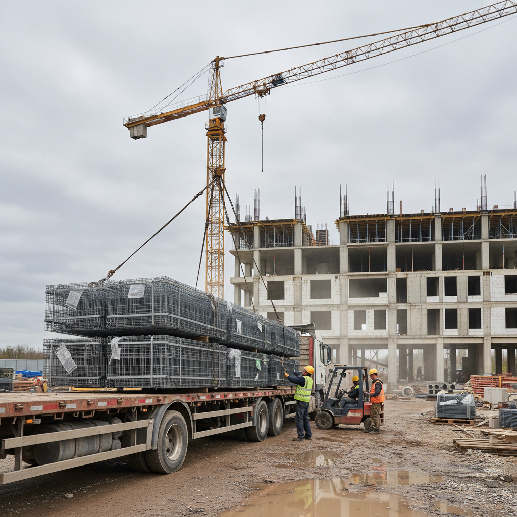
For logistics context, the image below shows bundled panels arriving to a commercial job site—staged to feed crews bay by bay.
Self-contained answer: Across residential podiums, commercial sidewalks, and municipal plazas, standardized 6×6 mesh paired with clear shop drawings yields predictable placements and tight crack control. Staging, cover, and laps are the levers that turn design intent into durable finishes.
Common Mistakes to Avoid
Avoid placing mesh directly on the subbase, under-lapping panels, or skipping chairs at bay edges. These shortcuts lead to wide cracks and callbacks. Pre-stage panels, secure laps at the specified length, and verify elevation and alignment before trucks arrive at the site.
- Walking mesh flat: Without supports, steel ends up at the bottom where it can’t control cracks.
- Short laps: Under-lapped joints act like unreinforced planes; confirm required lap length on drawings.
- Missing edge chairs: Perimeter areas sag first; concentrate supports at bay edges and around penetrations.
- Skipping pre-cuts: For sleeves and openings, cut and reinforce per detail before the pour.
- Poor curing: Early-age drying magnifies shrinkage; maintain curing to protect finish quality.
Align mesh detailing with our epoxy-coated rebar guide where exposure or deicing salts are present on your site.
Self-contained answer: Elevation, laps, and curing drive outcomes. When crews chair properly, lap correctly, and protect early-age concrete, WWR performs as designed and finish quality holds through seasonal cycles.
Coordinating Supply, Detailing, and Delivery with Dass Rebar
Dass Rebar integrates estimating, detailing, fabrication, delivery, and on-site assembly. We stock 6×6 mesh and coordinate shipments using a dedicated fleet so pour sequences stay on track across multiple Ontario job sites—even on days with two or more placements.
- Estimating: Fast, accurate takeoffs for 6×6 6/6, 9/9, and 10/10 options aligned to your drawings.
- Detailing: Placement diagrams keyed to bays, joints, sleeves, and pour breaks.
- Fabrication: Cutting and bending for rebar elements that interface with mesh.
- Delivery: Staged drops via a dedicated trucking fleet; predictable time windows across the GTA and Ontario.
- Assembly support: Coordination with your superintendent to minimize handling and speed deck turnovers.
This one-stop approach reduces the handoffs that create friction in real life. It’s the advantage of an MTO-approved partner backed by the JDASS CORP network—proven on residential, commercial, and infrastructure builds throughout Ontario.
Self-contained answer: With stock on hand, in-house drawings, and coordinated logistics, we keep WWR and related rebar deliveries aligned to your pour calendar—limiting downtime, rework, and schedule risk.
Share your slab or sidewalk drawings and pour dates. We’ll turn around a WWR takeoff, shop drawings, and a delivery plan that fits your schedule.
Frequently Asked Questions
These concise answers address common WWR questions from Ontario contractors. Use them in submittals and toolbox talks to keep teams aligned before pours begin.
Where should welded wire mesh sit in a slab?
Place WWR near the slab’s tension zone—typically around mid-depth—using chairs or dobies. Don’t lay it on the subbase and try to pull it up during the pour. Proper elevation is essential for crack control and is faster than fixes after finishing.
How much should WWR overlap?
Follow the engineer of record. A common rule of thumb is at least one full mesh spacing in each direction unless a longer lap is specified. Tie laps adequately so adjacent panels act as a single mat during placement and finishing.
Is mesh better than rebar?
They solve different problems. WWR excels at controlling shrinkage and temperature crack widths and speeds installation in large slab areas. Rebar provides primary strength and anchorage where loads are concentrated. Many projects use both by design.
Can I cut mesh around pipe sleeves?
Yes—pre-cut and reinforce around sleeves per the drawings. Add ties at the edges and maintain required cover. Preplanning avoids last-minute cuts that leave short laps or unreinforced planes.
Conclusion and Next Steps
Welded wire mesh reinforcement delivers fast, uniform crack control for slabs, sidewalks, and toppings. With correct elevation, laps, and staging, it performs predictably. Dass Rebar supplies standard 6×6 mesh and coordinates detailing and delivery across Ontario to keep your pour calendar intact.
Key takeaways
- WWR is a pre-welded grid that controls crack widths and distributes loads.
- Match spacing, gauge, and format to design and logistics; 6×6 10/10–6/6 covers many uses.
- Chair to elevation, lap per drawings, and stage panels to sustain pour pace.
- Use WWR with rebar where structural demands require both.
- Leverage Dass Rebar’s in-house teams and trucking fleet for predictable deliveries.
Ready to align your mesh, rebar, and delivery plan? Our team in Woodbridge supports projects across the GTA and Ontario—from estimating through on-site coordination—so your slabs place cleanly and finish right the first time.