Reading rebar shop drawings is the process of interpreting reinforcement plans, bar lists, and bend details so crews can place steel exactly as engineered. It clarifies bar sizes, shapes, spacing, cover, laps, and notes for field execution. For Woodbridge projects, it helps you avoid delays, reduce rework, and coordinate estimating, detailing, fabrication, and delivery.
By Navjot Dass • Dass Rebar
Last updated: 2026-07-01
Overview
This guide explains how to read rebar shop drawings with clarity: what symbols mean, how to follow bar marks and bending shapes, where to find spacing and cover, and how to confirm laps, hooks, and revisions. You’ll get a step-by-step method, best practices, checklists, and Ontario-ready examples using 10M, 15M, and 20M bars.
If you’ve ever stood over a slab layout wondering which bars go where, you’re not alone. We wrote this practical, field-tested playbook for general contractors, concrete contractors, developers, and construction managers who need accurate, buildable information—fast.
- What rebar shop drawings are and how they differ from structural plans
- How to read bar marks, bend shapes, splices/laps, hooks, and tags
- Where to verify cover, spacing, mesh, chairs, and supports
- Step-by-step checks you can run in under 20 minutes
- Ontario-ready examples using 10M, 15M, and 20M with typical values
- How Dass Rebar coordinates estimating → detailing → fabrication → delivery
What is “reading rebar shop drawings”?
Reading rebar shop drawings means interpreting reinforcement drawings, schedules, and bar lists to install the exact steel called for by the engineer. It includes decoding bar marks, bend shapes, sizes, spacing, laps, hooks, and notes so fabrication and field placement match design intent without rework.
Rebar shop drawings translate the structural design into fabricable, placeable instructions. They show bar-by-bar information: mark numbers, size (e.g., 10M, 15M, 20M), lengths, bends, hooks, and quantities. A typical drawing package contains:
- Plan views (slabs, walls, footings) with tags, callouts, and grids
- Sections and details for stairwells, shear walls, columns, beams, and piles
- Rebar schedules listing marks, sizes, lengths, shapes, and counts
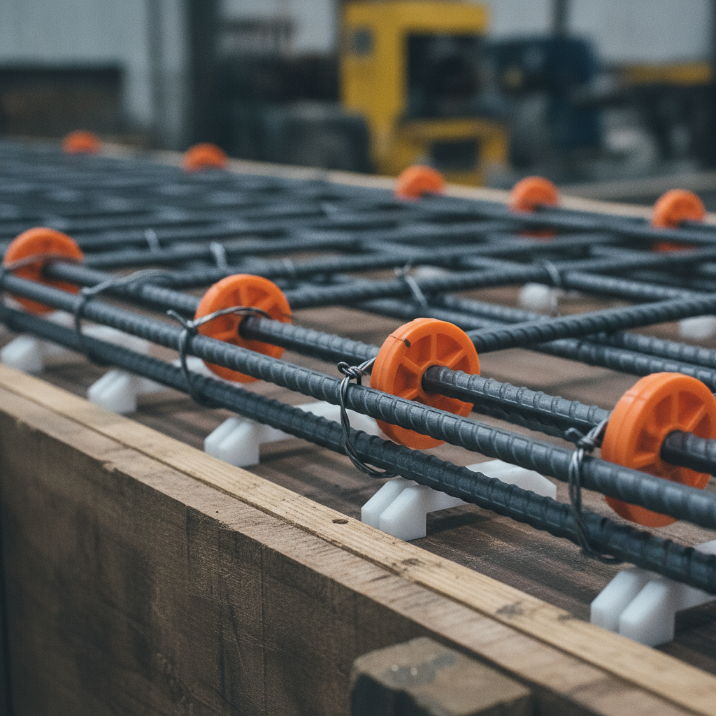
- Notes on cover, tolerances, laps, hooks, mechanical couplers, and epoxy or GFRB use
Canadian M-size bars are common in Ontario. Typical nominal diameters you’ll see: 10M ≈ 11.3 mm, 15M ≈ 16.0 mm, and 20M ≈ 19.5 mm. For quick mental math, lap lengths often run in the range of 40–60 bar diameters, while stirrup ties frequently appear at 200–300 mm (8–12 in) spacing—always confirm project notes.
To go deeper on drawing packages and coordination, see our internal primer on rebar shop drawings and our hands-on rebar detailing guide.
Why reading shop drawings matters
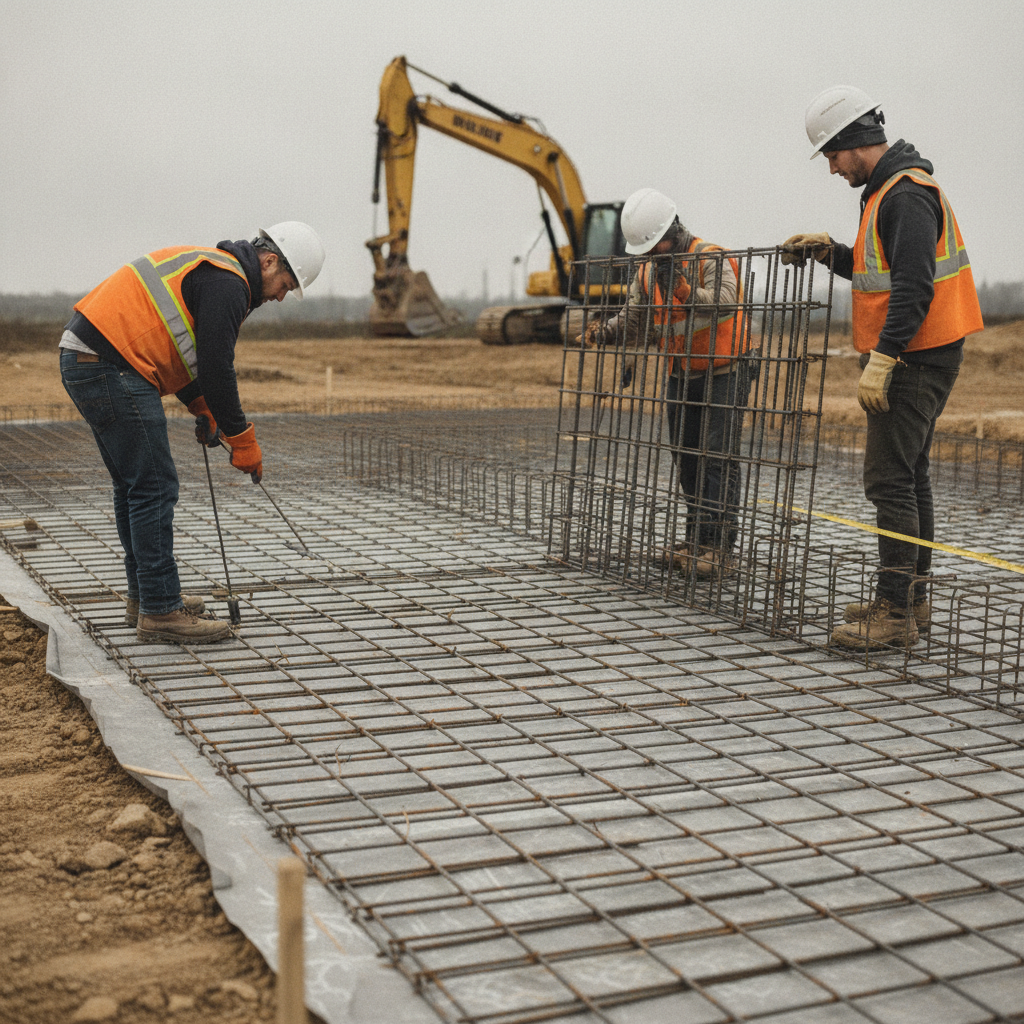
Accurate reading prevents field clashes, cuts waste, and keeps pours on schedule. It reduces RFIs, rebar returns, and last-minute fixes, aligning estimating, detailing, fabrication, delivery, and on-site assembly—so the steel shows up right and installs smoothly the first time.
Misread drawings cause avoidable pain: blown pour dates, rejected inspections, and emergency re-fab. A small interpretation error can ripple across an entire slab. One wrong lap or hook angle in a congested beam pocket can halt a placement crew for hours.
- Schedule protection: Even a 30-minute delay per pour adds up. Coordinated drawings reduce stoppages and rebar returns.
- Material efficiency: Accurate takeoffs align with fabrication lengths, minimizing waste. For example, aligning 15M bars to stock lengths reduces cutoffs and offcuts.
- Inspection readiness: Clear cover notes (often 20–50 mm for interior elements; higher at exposure) help pass checks the first time.
- Safety: Clear callouts prevent unplanned field bending, limiting strain and site hazards.
At Dass Rebar, we connect the full chain—supply, detailing, fabrication, delivery, and on-site assembly—so your drawing interpretation ties directly to what arrives on the truck.
How to read rebar shop drawings: a step-by-step workflow
Start with the sheet index and general notes, then read plans by grid. Cross-check sections and details, confirm bar marks against the schedule, and verify spacing, cover, laps, and hooks. Finally, reconcile revisions and quantity summaries with fabrication lists before mobilizing crews.
Use this nine-step workflow on every package. It’s fast, repeatable, and reduces uncertainty before steel hits the deck.
- Scan the cover sheet and index. Identify sheet count, latest revisions, and scope. Note any epoxy, GFRB, or welded wire mesh requirements.
- Read general notes and legends. Lock in bar size system (M sizes), chairs, spacers, couplers, lap philosophy (e.g., 45φ), and cover (e.g., 20–50 mm interior; more at exterior/soil).
- Walk the plan by grid. Trace major bars first (top/bottom directions), then secondary steel. Mark transitions at openings, drop panels, and shear strips.
- Jump to sections/details. Confirm beam/column cages, stirrups, wall horizontals/verticals, and hooks. Typical stirrup spacing shows 200–300 mm (8–12 in).
- Decode bar marks. Example: “B12 15M @200 T/B” reads as mark B12, 15M bars at 200 mm on top/bottom.
- Check the schedule. Verify each mark’s size, length, bend shape, quantity, and notes. Example mass per length: 10M ≈ 0.785 kg/m; 15M ≈ 1.570 kg/m; 20M ≈ 2.355 kg/m.
- Confirm laps and hooks. Laps often 40–60φ (project-specific). Standard 90° or 135° hooks appear in tight cages; note clearances.
- Reconcile quantities. Does the plan count match the schedule and fabrication list? If a beam has 10 marks but only 8 are listed, raise an RFI before fabrication.
- Review revisions and issue log. Circle delta triangles and confirm all superseded sheets are removed from the field set.
Pro tip: Add a sticky header to your checklist with project cover (e.g., slab, wall, footing), target pour window, and drawing revision number—so crews always align to the latest issue.
As you set up this workflow, our deeper explainer on rebar drawings explained gives visual examples that pair well with the steps above.
Types of views, notations, and how to decode them
Plans show the layout by level or element; sections show depth, layering, and cages; schedules list bar-by-bar instructions. Learn the common tags, abbreviations, and bend shapes so you can connect each callout in plan to a mark and shape in the schedule.
Plan views and callouts
Plan sheets locate bars by grid, span, and opening. You’ll often see directional arrows, “top” vs “bottom” tags, and add-ons at openings. Spacing like “@200” (200 mm) and mesh notes (e.g., 6×6 6/6) are common on slabs.
- Main direction bars: Typically noted first with spacing (e.g., 15M @200 top).
- Distribution bars: Perpendicular to main direction, often @300.
- Edge/thickened zones: Heavier steel near edges, openings, or drop panels.
- Mesh: Welded wire mesh may supplement or replace certain bar mats on slabs-on-grade.
Sections, details, and cages
Sections clarify layers, bar cover, and stirrup or tie patterns. Beam stirrups often step from 100–150 mm at supports to 200–300 mm at midspan. Wall cages pair verticals (e.g., 15M @200) with horizontals (e.g., 10M @250).
- Hooks: 90° or 135° hooks in tight spacing to lock cages; note hook direction.
- Development and laps: Laps commonly 40–60φ; development lengths vary with concrete strength and coating.
- Cover: Typical interiors 20–50 mm; exterior/soil/contact areas increase cover.
Schedules, marks, and shapes
The schedule resolves each callout into fabrication data. Shape codes define bends and lengths; the table notes size, length, angle, hook, and quantity per mark. Check that bent dimensions allow for clear fit in congested zones.
- Example mark: “C21 – 10M – Shape S2 – L=2200 – Qty 28 – 90° hooks both ends.”
- Mass checks: Cross-verify quantities by mass per meter to sanity-check totals.
- Finish flags: “E” for epoxy-coated bars or “GFRB” called out specifically in notes.
Common abbreviations and tags
- T/B: Top/bottom mat
- EW: Each way (two directions)
- EF: Each face (walls)
- Typ.: Typical (repeats unless noted)
- CLR: Clear cover
- O/C: On center (spacing)
Need more visual context? Our Ontario-focused concrete rebar guide outlines slab, wall, and beam patterns used across GTA jobs.
At-a-glance table: where key info lives
Use this quick table to locate critical information fast: cover and spacing live in notes and sections; bar sizes and shapes live in schedules; plan sheets carry the layout and mark tags you’ll match back to the schedule before fabrication.
| Drawing element | Where to find it | What to verify | Typical values (Ontario) |
|---|---|---|---|
| Bar sizes | Rebar schedule | 10M/15M/20M correct per plan | 10M≈11.3 mm; 15M≈16.0 mm; 20M≈19.5 mm |
| Spacing | Plans, notes | @200, @250, @300 alignment with mat area | 200–300 mm (8–12 in) common |
| Cover | Sections, notes | Formed faces vs soil/contact | 20–50 mm interior; higher at exposure |
| Laps/hooks | Details, notes | Lap length basis and hook angles | Laps ~40–60φ; 90°/135° hooks |
| Finish/coating | Notes, schedule flags | Epoxy, GFRB, or black | Epoxy at harsh exposure |
Best practices that prevent rework
Run a pre-pour drawing review, align fabrication lists with schedules, and tag bundles by mark for quick field identification. Confirm cover hardware and mesh in advance, and keep superseded sheets off site to prevent accidental installs.
Pre-pour checklist
- Verify latest revision triangles on every sheet in the set.
- Reconcile plan counts to schedule quantities and the fabrication list.
- Confirm cover requirements and ensure chairs/spacers meet them.
- Check lap assumptions and hook types against details.
- Lay out congested cages on paper before the crew bends on site.
Fabrication and delivery alignment
- Bundle bars by mark and label bundles so the foreman can find C12, B7, etc., fast.
- Sequence deliveries to match pour breaks and crane windows.
- For 15M-heavy mats, align cut lengths to reduce offcuts and handling time.
Field placement habits
- Use string lines and lasers to keep spacing uniform across large mats.
- Pre-stage mesh rolls (e.g., 6×6 6/6, 9/9, 10/10) at grid intersections.
- Place chairs first at 800–1200 mm (32–48 in) to hold cover while tying.
- Tag any field-adjusted bars and report for as-built updates.
For a deeper dive into how we structure drawings to be field-friendly, see our detailing best practices.
Local considerations for Woodbridge
- Coordinate deliveries around Queen St / Highway 50 traffic peaks to avoid crane standby; morning windows are usually smoother for receiving bundles.
- In winter pours, plan extra time for heating and cover hardware; frozen ground near Fogal Rd / Highway 50 can shift slab-on-grade prep and mesh staging.
- When our in-house detailing teams flag congested cages, we pre-bundle marks by pour break, reducing on-site reshuffling in tight Woodbridge lots.
Tools, resources, and how Dass Rebar supports you
Use a consistent checklist, mark-up tools, and bar schedule cross-checks. Dass Rebar connects estimating, detailing, fabrication, delivery, and assembly so the drawings you read match the steel that arrives—improving accuracy across Ontario projects.
In our experience, teams that standardize tools spot conflicts earlier and reduce RFIs. A simple kit speeds interpretation:
- Printed set in order with cover sheet and index on top
- Colored pens for top mat, bottom mat, and add-ons at openings
- Scale/roll-up tape to validate spans and bar spacing on paper
- Checklist aligned to the nine steps earlier
- Fabrication list from your supplier to reconcile quantities
How we plug in on Ontario jobs:
- In-house estimating to produce accurate takeoffs and early bar counts
- In-house detailing creating shop drawings and bend lists that read clearly
- Fabrication with cutting and bending tuned to your pour sequences
- Delivery using a dedicated trucking fleet across the GTA and province
- On-site assembly support and coordination when you need an extra set of hands
If you’re aligning rebar choices with exposure conditions, our overview of how rebar strengthens concrete and this 400W rebar reference offer quick refreshers.
Mini examples from Ontario projects
Use these short scenarios to see how interpretation impacts schedules and quality. Each example shows the drawing cue, the potential pitfall, and the simple action that kept work moving—based on real patterns we see across GTA projects.
Slab-on-grade with mesh and 15M add-ons
Scenario: The plan calls for 6×6 10/10 mesh with 15M add bars @200 at door openings. The schedule shows a short 15M shape with 90° hooks at each end.
- Pitfall: Crew assumes mesh alone covers openings and skips the add bars.
- Action: Mark openings in color, pre-cut 15M add bars, and bundle by opening. Confirm cover using chairs set at 900 mm (36 in).
- Result: Add bars installed in 20% less time than the prior pour; inspector signed off without comments.
Shear wall cage congestion
Scenario: A wall section shows vertical 20M @200 EF and horizontal 15M @250 EF with boundary elements at ends.
- Pitfall: Hooks clash at corners; crew tries to bend on site.
- Action: Detailing releases alternate hook directions and staggers laps by 600 mm (24 in). Fabrication bundles marks for each lift.
- Result: Cage tied without field bending; crane time met, pour held schedule.
Beam stirrup transitions
Scenario: Beam B4 stirrups are 10M @150 near supports, transitioning to @250 at midspan; top/bottom bars are 20M continuous with lapped splices centered over supports.
- Pitfall: Without a transition highlight, crew misses the spacing change.
- Action: Mark transition gridlines in red; pre-count stirrups for each zone.
- Result: Zero spacing NCRs; beam passed inspection first try.
Stair flight details
Scenario: Sections show bent 10M tread bars and 15M sloped stringer bars with specific hook orientations.
- Pitfall: Hooks reversed on first flight; delay before pour.
- Action: Tag hook direction on drawings and bundle left/right separately.
- Result: Second flight installed 30 minutes faster than baseline.
For more examples of how we stage and sequence work, check our GTA-focused steel reinforcement guide and regional rebar guide.
Frequently Asked Questions
Here are quick answers to common questions about reading rebar shop drawings. Each response is concise and field-ready, so you can resolve issues before they slow down your pour schedule.
What’s the fastest way to verify bar marks?
Match each plan callout to the schedule, then confirm size, shape code, length, and quantity. Highlight marks by color (e.g., 10M blue, 15M red) and reconcile totals with the fabrication list before accepting delivery.
How do I find cover and spacing in drawings?
Cover is typically shown in sections and general notes; spacing is called out on plan views. Look for tags like “@200” for spacing and “CLR” for clear cover. Always confirm higher cover at exterior or soil-facing elements.
When should I request an RFI?
Submit an RFI when plan counts don’t match the schedule, when laps/hooks are unclear, or when revisions conflict. It’s better to pause fabrication than rework on site. Flag conflicts early and attach redlined sketches for clarity.
Do I read M sizes differently than # sizes?
No, the reading process is the same. In Ontario, you’ll mostly see metric M sizes like 10M, 15M, and 20M. Just remember their nominal diameters (≈11.3, 16.0, and 19.5 mm) and verify lap and development notes specific to each project.
Key takeaways
Use a repeatable workflow: read notes, trace plans, resolve marks in the schedule, and reconcile with fabrication before mobilizing. Confirm cover, spacing, laps, and hooks—and keep superseded sheets off site to prevent install errors.
- Reading rebar shop drawings is a learnable workflow, not guesswork.
- Mark-by-mark verification prevents returns and pour-day surprises.
- Cover, spacing, laps, and hooks must be confirmed before tying.
- Label bundles by mark to save minutes on every placement.
- Use Ontario-common 10M, 15M, 20M values as quick checks, but follow project notes.
Conclusion and next steps
Shop drawings are your bridge from design to placement. Read them in a consistent order, resolve every mark in the schedule, and tie your interpretation to fabrication and delivery plans. That’s how pours hold, inspections pass, and rework disappears.
Here’s what to do now:
- Adopt the nine-step reading workflow on your next pour.
- Align your drawing review with fabrication and delivery sequences.
- Standardize a color system and bundle labels by mark.
- Have us pressure-test your set before you fabricate.
Ready for a fast, practical review? Share your latest set, and our detailing team in Woodbridge will flag clashes, confirm laps and hooks, and align quantities with fabrication. Start with our in-depth page on rebar shop drawings and connect with our team from there.
Get a shop drawing sanity check
Before you cut steel, have us run a 20-minute review aligned to your pour breaks. We’ll reconcile plans, schedules, and fabrication lists. Explore how we approach it in our detailing workflow.