Retaining wall rebar detail is the precise layout of bar sizes, spacing, cover, hooks, laps, and anchorage for a wall’s footing and stem. It converts design intent into buildable instructions crews can follow. In Woodbridge, clear details help pass inspections fast, reduce rework, and keep pours on schedule—even on tight sites with utilities nearby.
By Navjot Dass — Dass Rebar • Last updated: 2026-06-27
Above-fold summary
This complete guide explains what retaining wall reinforcement detailing is, why it matters, and how to execute it step-by-step. You’ll get typical bar sizes, spacing, lap and hook guidance, buildable drawings tips, inspection checklists, case examples, and tool recommendations tailored to Ontario job sites and Woodbridge logistics.
- Understand core elements: footing mats, stem bars, cover, splices, and hooks
- Follow a field-ready workflow from design inputs to placement
- Review common wall types and where steel does the work
- Apply best practices that speed inspections and prevent rework
- Use checklists, templates, and bar-mark conventions crews trust
What is “retaining wall rebar detail”?
Retaining wall rebar detail defines the exact bar sizes, spacing, bends, hooks, laps, and cover for both the footing and stem. It translates calculations into clear shop drawings, placing plans, and bar marks so fabrication, delivery, and on-site tying run smoothly and inspectors can verify compliance quickly.
Great details remove guesswork. They specify:
- Footing steel: bottom and top mats, heel/toe emphasis, keyways, dowels, and starter bars
- Stem steel: vertical tension bars at the backfill face, horizontal ties for crack control
- Anchorage: development lengths, 90°/135° hooks, and embedment into toe/heel
- Connections: corners, returns, steps, pilasters, and end walls that maintain the tension path
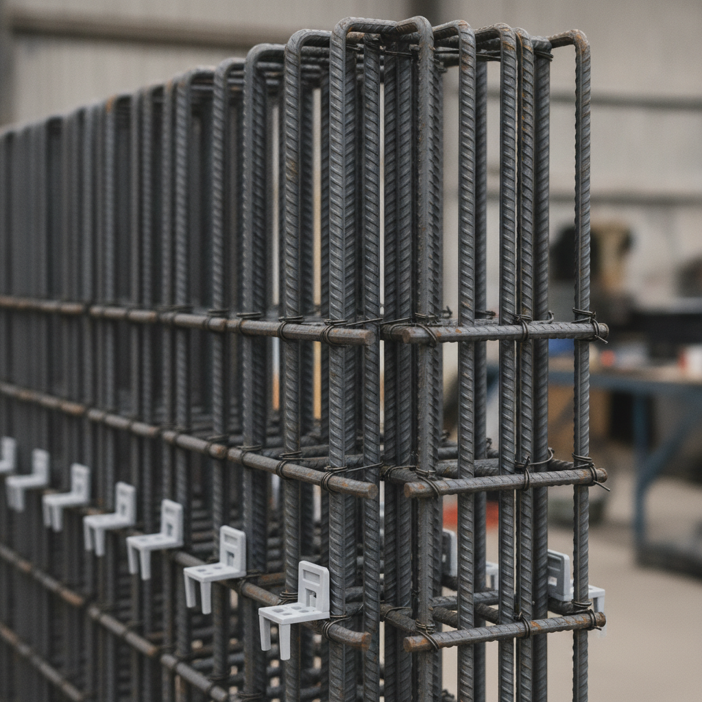
- Accessories: chairs, spacers, supports, and tie-wire locations that protect cover
In our experience supporting Ontario projects, clean detailing can cut pre-pour RFIs dramatically and keep crews focused on tying—not troubleshooting.
Why rebar detailing matters for retaining walls
Detailing quality drives capacity, crack control, longevity, and inspection speed. Accurate bar lists and lap schedules reduce field errors and align fabrication and delivery with pour dates. Clear placement drawings mean crews place steel once and pass the first inspection.
- Safety and performance: correct verticals at the tension face resist overturning; heel mats curb sliding.
- Durability: proper cover (often 3 inches against soil) and epoxy-coated options limit corrosion.
- Speed: legible shop drawings and tags reduce walkdown time and punch items.
- Logistics: bar lists connect to bending capacity and delivery windows—no last-minute scrambles.
We routinely coordinate detailing, fabrication, and on-time rebar delivery so GTA pours stay on schedule.
How retaining wall rebar detailing works (step-by-step)
A reliable workflow confirms loads and soils, selects the wall type, sizes bars and spacing, models laps and hooks, coordinates penetrations/steps, then produces shop drawings that drive fabrication, delivery, and field placement. Each loop tightens clarity and reduces site uncertainty.
Field-ready workflow you can follow
- Confirm design inputs: wall height, retained soil type, water table, surcharge (e.g., traffic), and frost depth.
- Select system: cantilevered concrete, counterfort, gravity, or MSE with concrete/segmental facing.
- Lay out footing: width and thickness, heel/toe proportions, keyway, drains, and geotextiles.
- Choose bar sizes: vertical stem bars (often 10M–15M; heavier walls may use 20M), horizontal ties, and footing mats.
- Define laps and hooks: splice class (tension/compression), lap lengths (increase for epoxy), and stagger patterns.
- Coordinate features: steps, corners, returns, pilasters, and utility sleeves/weep holes.
- Produce shop drawings: bar marks, bending schedules, and scaled placing plans crews can read.
- Fabricate and tag: cut, bend, bundle, and label by bar mark for fast staging and tying.
- Deliver and place: stage by sequence, protect cover with chairs/spacers, and tie to marks.
Need help turning calcs into buildable drawings? Our in-house team handles rebar detailing end-to-end—from takeoff to tagged bundles—so your field crew simply follows the plan.
Common retaining wall types and typical reinforcement
Most job-built walls are cantilevered concrete, counterfort, gravity/mass, or MSE with segmental facing. Each shifts where steel works hardest—stem tension for cantilevers, heavier heel mats for sliding, or mechanical connections in MSE systems.
At-a-glance comparison
| Wall Type | Typical Reinforcement | Notes |
|---|---|---|
| Cantilevered concrete | Vertical bars at backfill (tension) face; horizontal ties; bottom mat under heel; doweled key | Common for 4–20 ft; efficient steel use; quick to form and place |
| Counterfort | Diagonal webs tying stem to footing; heavier stem/heel mats; closely spaced verticals | Economical for tall walls; reduces stem bending |
| Gravity/mass | Minimal steel; temperature/shrinkage bars; thick sections | Good for short heights; check bearing and sliding |
| MSE + facing | Soil reinforcement (strips/geogrid) + doweled concrete/segmental facing | Modular; strong for poor access or phased work |
For deeper foundations and footing steel, see our footing rebar guide with step-by-step checks crews can run in minutes.
Best practices for retaining wall reinforcement
Make details buildable: prioritize adequate cover, splice classes, workable lap staggering, and clear bar marks. Protect clearances with chairs and spacers, and pre-model congested areas. Draw steps, corners, and sleeves at large scale so no one cuts primary bars in the field.
Determinants of durable performance
- Cover targets: 3 in. against earth is a common minimum; 2 in. at formed faces (verify exposure category).
- Splice logic: increase lap lengths for epoxy, tension splices, and larger bars; stagger to ease congestion.
- Development: ensure hooks and extensions fully anchor into the heel/toe and along returns.
- Bar supports: use chairs that won’t sink; add stand-offs at vertical faces to keep cover true.
- Coatings/materials: epoxy for deicing or chloride splash; Glass Fiber Reinforcing Bars (GFRB) for corrosion-critical zones.
Want the bigger picture on materials? We outline options and pros/cons in our concrete rebar guide and steel reinforcement suppliers guide.
Local considerations for Woodbridge
- Coordinate deliveries around Queen St / Highway 50 peak traffic; stage bundles by bar mark so short windows still work.
- Plan winter pours with frost protection at heel mats; chair bases that won’t punch into frozen subgrade near Fogal Rd / Highway 50.
- For tight urban lots, pre-model one bay with 15M verticals and 10M horizontals to verify vibrator access and cover.
Tools, codes, and resources you’ll actually use
Pair code rules with practical templates: lap/cover tables, bending schedules, and simple bar-mark conventions. Use BIM for complex congestion; otherwise, clean 2D placing drawings move faster in the field and on inspections.
- Codes: use the governing concrete code for development, splices, hooks, and cover.
- Guides: earth pressure and drainage references help refine heel mats and weeps.
- Software: CAD/BIM for placing drawings; spreadsheet lap calculators; bar list generators.
- Templates: bar list + tag format, inspection checklists, and a corner/step callout sheet.
For crews new to cages, our rebar cages basics article covers tying patterns and tag reading on busy pours.
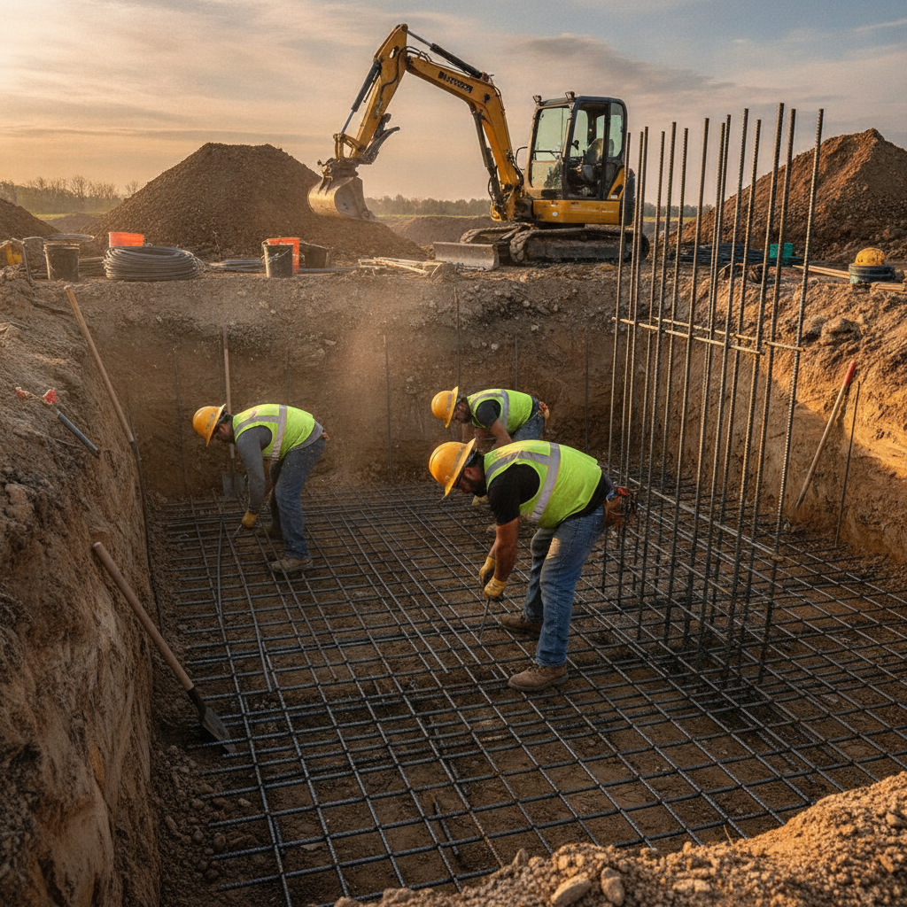
Step-by-step site checks before the pour
Walk the trench, verify subgrade and drains, confirm chairs/spacers, then check bar size, spacing, laps, and hooks against the placing plan. Tag conflicts and fix them before concrete. A 15-minute checklist now can save days and a full re-tie later.
- Confirm subgrade elevation, drain slope (e.g., 1% minimum where specified), and daylight outlets.
- Measure footing width, heel/toe, and keyway dimensions at several stations.
- Check bar diameters, vertical spacing (often 8–12 in.), and cover at soil faces (often 3 in.).
- Verify laps/hooks at steps and joints; stagger splices per plan.
- Inspect chairs/spacers and stand-offs that maintain cover during vibration.
- Dry-fit sleeves/block-outs for utilities and weeps; add ties around openings.
- Stage bundles by bar mark along the wall in sequence; protect epoxy coatings.
Document with time-stamped photos. Inspectors respond well to clear evidence and tidy staging.
Bar sizes, spacing, laps, and hooks
Choose vertical stem bars to resist bending at the backfill face, horizontal bars to control cracking, and footing mats to resist sliding and bearing. Use code-based lap and hook lengths, stagger splices, and leave room for consolidation so minimum cover isn’t lost.
- Typical sizes: stems commonly use 10M–15M; taller/heavier loads may require 20M.
- Spacing ranges: 8–12 in. for verticals; 12–16 in. for horizontals, adjusted by design.
- Laps: tension splices often govern; epoxy-coated bars require longer laps—verify tables.
- Hooks: 90° or 135° per location; ensure full embedment into heel/toe and returns.
Working with larger-bar stems? Our 20M rebar guide highlights bending radii, handling, and tying tips that keep production moving.
Detailing corners, steps, and penetrations
Corners, height steps, and pipe penetrations create most field errors. Wrap corners with continuous L- or U-bars, extend verticals through steps, sleeve pipes with added ties, and avoid cutting primary bars. Draw these at large scale on placing plans to remove ambiguity.
- Corners: maintain the tension path with continuous bars; avoid “butt” laps at the corner kink.
- Steps: carry verticals past the step and lap new bars above/below per splice class.
- Pipes: use sleeves; add hoops/stirrups flanking openings; don’t cut main bars.
- Returns: develop stem bars fully into returns to avoid crack starters.
These details are small on paper but huge on-site. A single missed corner wrap can telegraph a crack line across the face within a season.
Materials and coatings: steel, epoxy, and GFRB
Use carbon steel (e.g., Grade 400W/500W equivalents) for most walls, add epoxy where deicing salts or chlorides exist, and consider Glass Fiber Reinforcing Bars (GFRB) where corrosion risk or magnetic neutrality matters. Match schedules to supply lead times and bending capacity.
- Carbon steel: predictable behavior, fast bending, broad availability.
- Epoxy-coated: added protection in splash zones and exposed faces; handle carefully to avoid coating damage.
- GFRB: corrosion-proof and light; different lap rules and no yielding—coordinate with design.
We stock common sizes and welded wire mesh, and we’re an MTO-approved supplier—backed by JDASS CORP—so materials arrive when you need them.
Drainage and backfill integration (don’t skip this)
Reinforcement won’t save a wall from poor drainage. Include weep holes or drains, free-draining backfill, and geotextile separation. Good drainage reduces hydrostatic pressure and limits frost action, protecting both the wall and the rebar envelope.
For context on non-structural basics crews must still get right, this drainage guide outlines gravel, pipe slopes, and weep strategies field teams can visualize quickly. While not a structural code, it’s a useful operational reference.
- Perforated pipe: continuous slope to daylight or sump; protect with filter fabric.
- Backfill: free-draining aggregate against the stem; compact native soils in lifts.
- Weeps: consistent spacing; avoid blocking with mortar or debris.
Mini case examples from Ontario jobs
Tight access, winter conditions, and surprise utilities are the usual culprits. Modeling one congested bay, staging bundles by bar mark, and upgrading to epoxy at exposure zones have helped crews place once and pass inspections without schedule slips.
- Urban infill (GTA): staged bundles per bay preserved a single-lane access; pour hit the morning window.
- Winter work: chair bases tested on frost; no cover loss during vibration; inspector signed off in one visit.
- Utility clash: large-scale sleeve detail eliminated field cuts; added hoops controlled stress around the opening.
These small upstream moves avoided multi-day delays. That’s real time saved for supers and crews.
Spec and shop drawing review checklist
Use a short review loop to close gaps: verify exposure category and cover, check lap/anchor tables, confirm corner/step/penetration details, align bar marks with bending capacity, and set delivery sequencing. The tighter the loop, the fewer RFIs downstream.
- Exposure and cover confirmed (soil face, formed faces, splash zones)
- Lap and hook lengths per code tables; epoxy adjustments applied
- Corner wraps, steps, and sleeve details drawn at large scale
- Bar marks legible; bending radii within shop capacity
- Bundles sequenced; tags match placing plan stations
- Inspection photos planned (pre-pour signoff path defined)
Our team’s integrated detailing basics and fabrication workflow reduces revision cycles and gets tagged steel on site, on time.
Selecting wall materials and facing systems
Concrete stems with cast footings are common for 4–20 ft heights, but segmental block facings and MSE systems can speed access-limited sites. Choose the system first, then tailor reinforcement to that path. Don’t force a single detailing pattern on every wall.
If you’re comparing facings and soil systems from a practical field lens, this materials overview offers visual cues crews recognize. For structural design, always defer to the engineer of record and the governing code.
- Cast-in-place: predictable reinforcement; straightforward inspections
- Segmental facing: modular; coordinate geogrid and facing dowels early
- MSE: great for height and phasing; ensure backfill quality and compaction
Planning access and traffic windows
Logistics matter as much as math. Stage bundles by bar mark, schedule deliveries to match pour windows, and pre-assign a tying sequence. Short traffic windows near key intersections mean your first load needs to go straight to work—no shuffling.
In Woodbridge corridors, narrow laydown areas and traffic near key nodes can compress work windows. A practical primer on sequencing options and pacing is useful; this design-focused explainer includes site planning visuals field teams find helpful when aligning scope and access.
- Bundle sequencing matches tie order and pour breaks
- First truck = first bay; second truck = steps/corners and sleeves
- Backfill and drainage crews queued to follow forming
Frequently Asked Questions
These answers address common retaining wall reinforcement questions from PMs and superintendents. Use them to make quick field decisions and keep inspections moving.
Where should the tension face bars go in a cantilever wall?
In a typical cantilevered wall, vertical bars sit near the backfill side—the tension face of the stem. The footing’s bottom mat concentrates under the heel to resist sliding and overturning, with minimum cover maintained against soil.
How much lap length do I need for vertical bars?
Lap length depends on bar size, coating, concrete strength, and whether the splice is in tension or compression. Use the governing concrete code’s tables and increase lengths for epoxy-coated bars. Always stagger splices to reduce congestion and ease vibration.
What cover is required on the soil side of the footing?
A common minimum is 3 inches of cover against earth for cast-in-place concrete, unless exposure categories or local codes require more. Maintain cover with stable chairs or dobies that won’t punch into the subgrade during placement and vibration.
Key takeaways and next steps
Detail for buildability, verify cover and laps, sequence bundles, and document pre-pour checks. These habits prevent rework and streamline inspections. Align reinforcement with drainage and access planning, and your wall will perform and pass on the first try.
- Use clear placing drawings with large-scale callouts for corners, steps, and sleeves
- Protect minimum cover with the right chairs and spacers—especially at soil faces
- Stage bundles by bar mark to match tie order and traffic windows
- Photo-document checks to accelerate pre-pour approvals
Ready to turn calculations into buildable drawings and tagged bundles? Our in-house team can help with estimating, detailing, fabrication, delivery, and on-site assembly across Ontario. Let’s plan your next wall in Woodbridge—start with a quick consultation.
Need stamped shop drawings and tagged steel that arrives when you pour? Explore our integrated rebar detailing services to reduce RFIs and keep production moving.