
Last updated: October 2026
On Ontario drawings and technical documents, you may see the terms welded wire reinforcement, welded wire mesh, or welded wire fabric rather than “weld mesh.” They describe the same broad product category: steel wires joined at regular intersections to create a two-directional grid. The exact product, strength, spacing, lap, and placement requirements still come from the project drawings and specifications.
Dass Rebar supports contractors, developers, and concrete specialists with estimating, detailing, fabrication, project management, delivery, and on-site assembly. Its Woodbridge yard at 370 New Enterprise Way stocks commonly requested reinforcement products and supports projects across the GTA and Ontario with coordinated trucking and project scheduling.
What this welded wire reinforcement guide covers
This guide explains where WWR is useful, how to compare it with reinforcing bar, and what to verify before concrete arrives. It is intended to help project teams ask better questions; it does not replace the structural drawings, approved shop drawings, specifications, or direction from the design professional.
- How welded wire reinforcement is made and what it does inside concrete.
- How spacing, wire designation, sheets, and rolls affect selection.
- When mesh is suitable and when reinforcing bar is the better solution.
- How to coordinate laps, chairs, cover, joints, openings, and inspection.
- How Ontario standards and delivery planning affect a reinforcement package.
For a broader comparison of reinforcement systems, see this concrete reinforcing bar guide. For product terminology and common applications, the steel wire mesh overview provides useful background.
What is weld mesh reinforcement?
Weld mesh reinforcement is a grid of steel wires joined at their intersections, usually by resistance welding. The factory-controlled spacing creates a repeatable reinforcement pattern that can be supplied as flat sheets or coiled rolls. In concrete, the grid provides distributed steel that helps manage tensile stresses and limit the width and concentration of cracks.
WWR does not make concrete immune to cracking. Concrete still shrinks, moves with temperature and moisture, and responds to subgrade movement, restraint, loads, and construction conditions. Reinforcement works with appropriate joints, curing, subgrade preparation, and concrete placement to make cracking more controlled and serviceable.
How mesh designations are read
A designation such as 6-inch by 6-inch at 6/6 describes the spacing and wire designation in the two directions. The first part identifies the approximate grid openings; the paired numbers identify the wire size or reinforcement designation used by the supplier and specification. A 6/6 product is not automatically appropriate for every 6-inch slab, so selection must follow the design rather than the slab thickness alone.
Dass Rebar confirms standard configurations including 6-inch by 6-inch mesh at 6/6, 9/9, and 10/10. Availability, sheet dimensions, roll format, coating, and lead time should be confirmed during estimating because the practical choice can affect handling, supports, cutting, and site access.
Why use welded wire reinforcement in concrete?
The main reason to use WWR is distributed crack control. When tensile strain develops, the grid helps share that demand across many wires instead of allowing a single crack to open as freely. The result depends on steel area, spacing, concrete properties, restraint, joint layout, support conditions, and placement accuracy.
A second benefit is installation consistency. A prefabricated grid can cover a large area without crews measuring and tying every individual bar intersection. That can reduce handling and tying work, but it does not remove the need for chairs, ties, laps, edge reinforcement, openings reinforcement, or inspection.
Where WWR is commonly considered
- Slabs-on-grade, including commercial, industrial, residential, and warehouse floor areas.
- Sidewalks, driveways, light-duty pavements, and exterior concrete where the design calls for distributed reinforcement.
- Topping slabs and selected light walls or panels.
- Large, regular floor areas where a consistent grid is easier to install than individually placed bars.
WWR is only one part of a concrete system. A sound subgrade, correctly located joints, suitable concrete, curing, drainage, and protection from construction traffic all influence the finished result. Mesh that has been pushed to the bottom of a slab or displaced during vibration cannot perform as intended at the specified elevation.
How weld mesh reinforcement works inside a slab
As concrete dries and changes temperature, it develops tensile strain. Steel has much greater tensile capacity than concrete, so the grid engages as the surrounding concrete begins to crack. Closely distributed wires help transfer tension and keep cracks more evenly distributed and narrower than they might otherwise be.
Placement determines whether that theoretical benefit is available in the finished slab. Chairs or other approved supports hold the grid at the required elevation, while ties help keep sheets connected during concrete discharge, vibration, screeding, and finishing. The correct position is not simply “on the ground” or “somewhere near the top”; it is the position shown or required by the design.
Four placement controls that matter
- Elevation: Confirm the specified cover and reinforcement zone before the pour. A common field discussion for slab-on-grade work is the upper third, but the drawings govern.
- Laps: Overlap adjoining sheets or rolls as specified. A full mesh spacing is sometimes used as a field reference, but it is not a universal engineering requirement.
- Supports: Use stable chairs or supports at the spacing required to prevent sagging and flotation. The support plan should account for worker traffic and concrete placement.
- Joints and edges: Coordinate sawcuts, isolation joints, dowels, penetrations, perimeter bars, and additional reinforcement so the grid does not conflict with the crack-control strategy.

WWR sizes, formats, and selection decisions
Choosing mesh involves more than selecting the product that is available first. The design team and supplier should review wire designation, spacing, sheet or roll format, corrosion protection, dimensions, access, lifting, cutting, and the sequence in which each area will be poured.
| Decision | What it changes | What to verify |
|---|---|---|
| Wire designation | Steel area, stiffness, handling, and specified reinforcement capacity | Drawings, schedules, material requirements, and availability |
| Grid spacing | Distribution of reinforcement and fit around joints or penetrations | Specified spacing and coordination with openings |
| Sheet or roll | Flatness, coverage speed, cutting, lifting, and curl management | Bay geometry, access, crane or material-handling plan |
| Coating or alternative product | Durability and handling requirements in the exposure | Design requirements and compatible supports or accessories |
| Bundle size | Staging time, congestion, and unloading safety | Site access, crane zones, pour sequence, and crew capacity |
Sheets versus rolls
Flat sheets are often easier to position around columns, edges, openings, and embedded items. They generally require less effort to flatten than a roll that retains curvature. Rolls can cover long, open runs efficiently, but crews need a plan for uncoiling, straightening, supporting, lapping, and controlling the material during placement.
For either format, the reinforcement package should be labelled by pour or area. Pre-cutting is useful only when dimensions have been checked against the latest drawings and site conditions. A piece cut correctly for an earlier revision can create waste or a field change when penetrations move.
Welded wire mesh versus reinforcing bar
WWR and reinforcing bar are not interchangeable by default. Mesh is well suited to regular, distributed reinforcement in broad areas, while bars provide greater flexibility for concentrated forces, anchorage, bends, hooks, development length, and complex geometry.
| Project condition | WWR may be a good fit | Rebar may be preferred |
|---|---|---|
| Regular slab field | Fast, uniform distribution across open bays | Useful where the design specifies bar spacing or heavier steel |
| Beam, column, or pedestal | Usually supplementary or not typical as the primary cage | Better for anchorage, bends, hooks, and concentrated demand |
| Edges and penetrations | Can be trimmed and coordinated where permitted | Often preferred for additional bars and local strengthening |
| Complex geometry | Requires careful cutting and lap planning | Can be fabricated to the required shape |
| Large open floor plate | Efficient where the design calls for distributed mesh | May require more placing and tying labour |
Many projects use a combined system: WWR through the general slab field with reinforcing bars at edges, openings, joints, column strips, or areas of concentrated loading. The combination must be detailed rather than improvised in the field. The rebar and wire mesh selection article can help teams frame that discussion.
How to specify and place WWR correctly
Start with the approved design
Before ordering, identify the product designation, spacing, wire size, sheet or roll dimensions, laps, cover, supports, coatings, and any additional bars. Check that the takeoff reflects the current drawing revision and that openings, sleeves, pits, joints, thickened areas, and construction phases are included.
Do not use a generic “mesh throughout” note as a substitute for a coordinated reinforcement detail. The design should explain where reinforcement starts and stops, how it crosses joints, and what happens at edges or interruptions. If the drawings are unclear, resolve the question before fabrication or delivery.
Prepare the base and supports
- Confirm the subgrade or supporting surface is ready, stable, and at the required elevation.
- Protect vapor barriers and membranes from puncture during access, chair placement, and reinforcement handling.
- Use supports that remain stable under expected worker and concrete-placement traffic.
- Keep mesh clear of mud, excessive rust, oil, and debris that could interfere with placement or bond.
- Plan access routes so crews do not repeatedly walk across or drag the grid out of position.
Inspect before the pour
A pre-pour check should confirm product identification, spacing, laps, cover, support stability, edge conditions, openings, dowels, joints, and cleanliness. Measure representative locations rather than checking only the easiest corner. Record photographs and outstanding items so corrections are assigned before concrete discharge.
Ontario projects may also require records for delivered material, mill documentation, inspection, and approved placement details. The current framework should be checked against the contract requirements, but Ontario’s OPSS material and placement references are useful starting points: OPSS 1440 steel reinforcement requirements and the province’s OPSS 905 placement specification. Contract documents and the engineer’s direction remain controlling.
Ontario terminology, standards, and site responsibilities
Ontario technical sources commonly use “welded wire reinforcement,” “welded wire mesh,” or “welded wire fabric.” Using those terms in a request for quotation can reduce ambiguity, especially when the same buyer-facing project brief also uses “weld mesh reinforcement.” A supplier still needs the actual designation and drawings to quote the right material.
Ontario’s trade rules also recognize work involving reinforcing materials, including welded wire mesh, within the scope of reinforcing rodworker activities. The Ontario scope-of-practice regulation and the applicable site-safety and project requirements should be reviewed by the responsible contractor. Material supply does not replace competent placement, lifting, rigging, inspection, or supervision.
Where a project has unusual cover, fire-performance, corrosion, infrastructure, or exposure requirements, do not assume a standard 6-inch by 6-inch product is sufficient. Confirm the required material and detail against the current code, contract specification, and design professional’s instructions. A current Ontario building-code reference discusses specific wire mesh applications in concrete cover for fire performance, but that specialized condition should not be generalized to ordinary slab reinforcement.
Ontario delivery and logistics planning
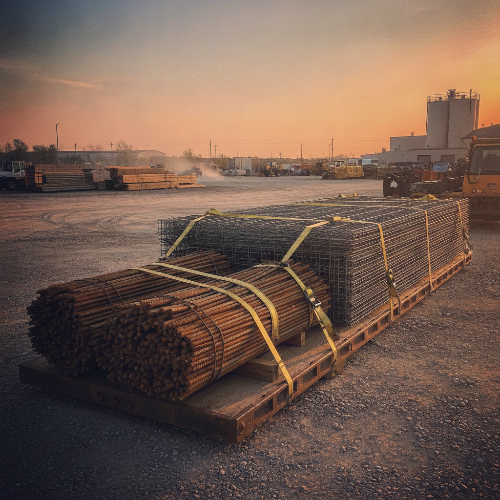
Reinforcement logistics affect productivity as much as material selection. Mesh that arrives too early can obstruct access and be damaged by other trades; mesh that arrives too late can leave finishers waiting for a truck or force rushed handling. A delivery plan should identify the pour date, unloading area, equipment, bundle weights, sequence, labels, and contact responsible for accepting the load.
Woodbridge and GTA delivery checklist
- Provide the latest pour schedule, site address, access restrictions, and delivery-window requirements.
- Separate bundles by building, grid, pour, or elevation so the first material unloaded is the first material needed.
- Confirm crane, telehandler, forklift, or manual-handling limits before selecting bundle sizes.
- Protect sheets and rolls from unnecessary site traffic, standing water, and damage during staging.
- Coordinate reinforcement arrival with pump setup, finishing access, inspection, and municipal or traffic restrictions.
From its Woodbridge base, Dass Rebar provides estimating, detailing, fabrication, project management, and dedicated trucking for reinforcement packages. The practical objective is not simply fast delivery; it is receiving identifiable material in an order that supports the crew’s pour sequence and keeps the work area usable.
Common WWR mistakes to prevent
Ordering by slab thickness alone
A five-inch or six-inch slab thickness does not identify the required mesh. Loads, support conditions, joints, exposure, construction sequence, and the design reinforcement schedule all matter. Order from the approved drawings rather than using a familiar product as a shortcut.
Letting mesh rest on the base
Mesh on the ground is not automatically in the correct reinforcement zone. Supports must hold it at the specified elevation, and the crew must protect that position while placing and finishing concrete.
Assuming a lap is always one square
Lap requirements vary with the product, design, loading, detailing rules, and project specification. Treat one mesh spacing as a possible field convention, not a universal rule. Confirm the required overlap and tie arrangement before the pour.
Ignoring interfaces
Openings, joints, dowels, perimeter conditions, columns, embeds, and thickened slabs frequently require details beyond the regular mesh field. Mark these locations on the placing plan and inspect them separately.
Frequently asked questions
Is weld mesh reinforcement the same as welded wire reinforcement?
In ordinary construction discussions, yes: “weld mesh reinforcement” is a buyer-facing phrase for welded wire reinforcement, welded wire mesh, or welded wire fabric. Product designations still need to be confirmed because spacing, wire size, format, coating, and strength are not defined by the phrase alone.
Should welded wire mesh go at the top or bottom of a slab?
Its position depends on the design and the function the reinforcement is intended to perform. For many slab-on-grade crack-control applications, the grid is placed in the upper portion, but the drawings govern the required cover and elevation. Chairs and inspection are needed to keep it there during the pour.
When should I choose mesh instead of rebar?
Mesh is often considered for regular slab fields, toppings, sidewalks, driveways, and other areas requiring distributed reinforcement. Rebar is generally more adaptable for beams, columns, pedestals, edges, openings, hooks, anchorage, and concentrated forces. A combined system may be appropriate when the design calls for both.
How can a contractor reduce WWR installation problems?
Use the latest drawings, specify the product precisely, label bundles by pour, plan stable supports, coordinate joints and openings, and complete a documented pre-pour inspection. Timed delivery and pre-cutting can help, but only after dimensions and the construction sequence have been checked.
Plan the reinforcement package before the pour
Weld mesh reinforcement is most effective when treated as a coordinated design, material, placement, and logistics decision. Select the product from the approved requirements, maintain its elevation with suitable supports, coordinate laps and joints, and inspect the complete system before concrete arrives.
For Ontario projects, Dass Rebar can support the package from estimating and detailing through fabrication, labelling, delivery, and on-site assembly. Contact Dass Rebar to discuss a mesh, rebar, or combined reinforcement requirement and align the material with your pour sequence.