
Foundation wall rebar detailing is the process of specifying bar sizes, spacing, laps, hooks, and cover so concrete walls resist soil pressure and cracking. For Woodbridge and GTA builds, Dass Rebar supports this with in-house detailing, fabrication, and delivery—so your foundation wall rebar detail is constructible, code-aligned, and on time.
By Navjot Dass • Last updated: 2026-05-25
Overview and Table of Contents
This guide explains foundation wall rebar detailing from first principles to field execution. You’ll learn what details mean, why they matter, how bars are placed, common methods, best practices, tools, and Ontario-focused examples—plus checklists you can use before pour day.
Use this overview to jump to what you need now:
- What is foundation wall rebar detail?
- Why it matters
- How detailing works
- Types and methods
- Best practices
- Tools and resources
- Case studies and examples
- FAQ
- Key takeaways
What Is Foundation Wall Rebar Detail?
A foundation wall rebar detail is the complete set of instructions for reinforcing concrete walls: bar sizes, spacing, lap splices, hooks, dowels, development lengths, cover, and placement diagrams. Good detailing translates design loads into shop drawings that are accurate, buildable, and ready for fabrication and inspection.
In practice, detailing turns calculations into a map installers can follow. It defines exactly where each bar starts, bends, laps, and terminates.
Core components you should expect
- Bar schedule: Identifies each bar mark, size, length, bends, and quantity.
- Plans and elevations: Show horizontal and vertical bar patterns, openings, and corners.
- Sections and details: Cover thickness, chairs, spacers, and construction joints.
- Notes and standards: Design code references (e.g., ACI/CSA alignment) and tolerances.
Dass Rebar’s in-house detailing team prepares shop drawings and bar lists that coordinate with fabrication and cut-and-bend, helping crews minimize rework when the formwork is standing and the clock is running.
Why Foundation Rebar Details Matter
Accurate rebar details prevent cracks, control deflection, and keep walls stable under soil pressure, frost, and surcharge. Clear drawings reduce field errors, speed installation, and pass inspections. The result is straighter walls, fewer callbacks, and durable basements that stay dry and safe.
Small misses compound fast in foundations. One mislocated lap or short hook can compromise performance at a corner or opening.
Direct benefits you can measure on site
- Fewer RFIs: Clear notes and typicals cut back-and-forth during tight schedules.
- Faster installs: Prefabricated cages and labeled bundles reduce handling time.
- Straighter walls: Correct bar spacing and chairs maintain cover and alignment.
- Inspection-ready: Consistent laps, hooks, and cover ease pre-pour checks.
We see this every week in Ontario. Coordinated reinforcing bar packages with precise bar marks let crews place steel with confidence, even on complex basements with jogs, step footings, and elevator pits.
How Foundation Wall Rebar Detailing Works
Detailing converts design intent into buildable instructions: choose bar sizes, set spacing, define laps and bends, then sequence fabrication and delivery. Field-friendly drawings reduce ambiguity so crews keep cover, maintain spacing, and tie bars that pass inspection the first time.
Here’s a practical breakdown of how we convert design into shop drawings and bundles that install smoothly.
1) Translate loads into bar patterns
- Vertical bars: Resist bending from lateral soil pressure; commonly placed at 12 to 24 inches on center.
- Horizontal bars: Control crack widths and tie the wall; typically 12 to 18 inches on center.
- Bar sizes: In Ontario, 10M (~#3), 15M (~#5), and 20M (~#6) are common for walls; selection depends on wall height, thickness, and backfill.
2) Define development, laps, and hooks
- Laps: Lap splices are often expressed as a multiple of bar diameter (db). For example, a standard tension lap can range around 40db depending on code, concrete strength, and confinement.
- Hooks: 90-degree or 135-degree hooks are used at corners, pilasters, and dowels to achieve anchorage.
- Dowels: Bars projecting from footings develop the wall; embedment and cover must be maintained.
3) Lock in cover, supports, and tolerances
- Concrete cover: Typical exterior faces need greater cover to protect against moisture; inside faces often have less cover. Maintain cover with chairs and spacers rated for footing/wall use.
- Tolerances: Keep spacing uniform; deviations can trigger inspection failures or performance issues.
- Accessories: Use noncorroding spacers with adequate bearing area to avoid point loading the form skin.
4) Coordinate fabrication and delivery
- Bar lists and tags: Every bundle gets a mark that matches the drawing schedule.
- Staging: Sequence deliveries by pour break—footings, then walls.
- Logistics: Dass Rebar’s dedicated trucking fleet improves timing to match your formwork cycle.
Getting these four steps right is what turns a clean design into a clean install. It’s also where a coordinated supplier–fabricator saves days, not hours.
Types/Methods/Approaches You’ll See on Site
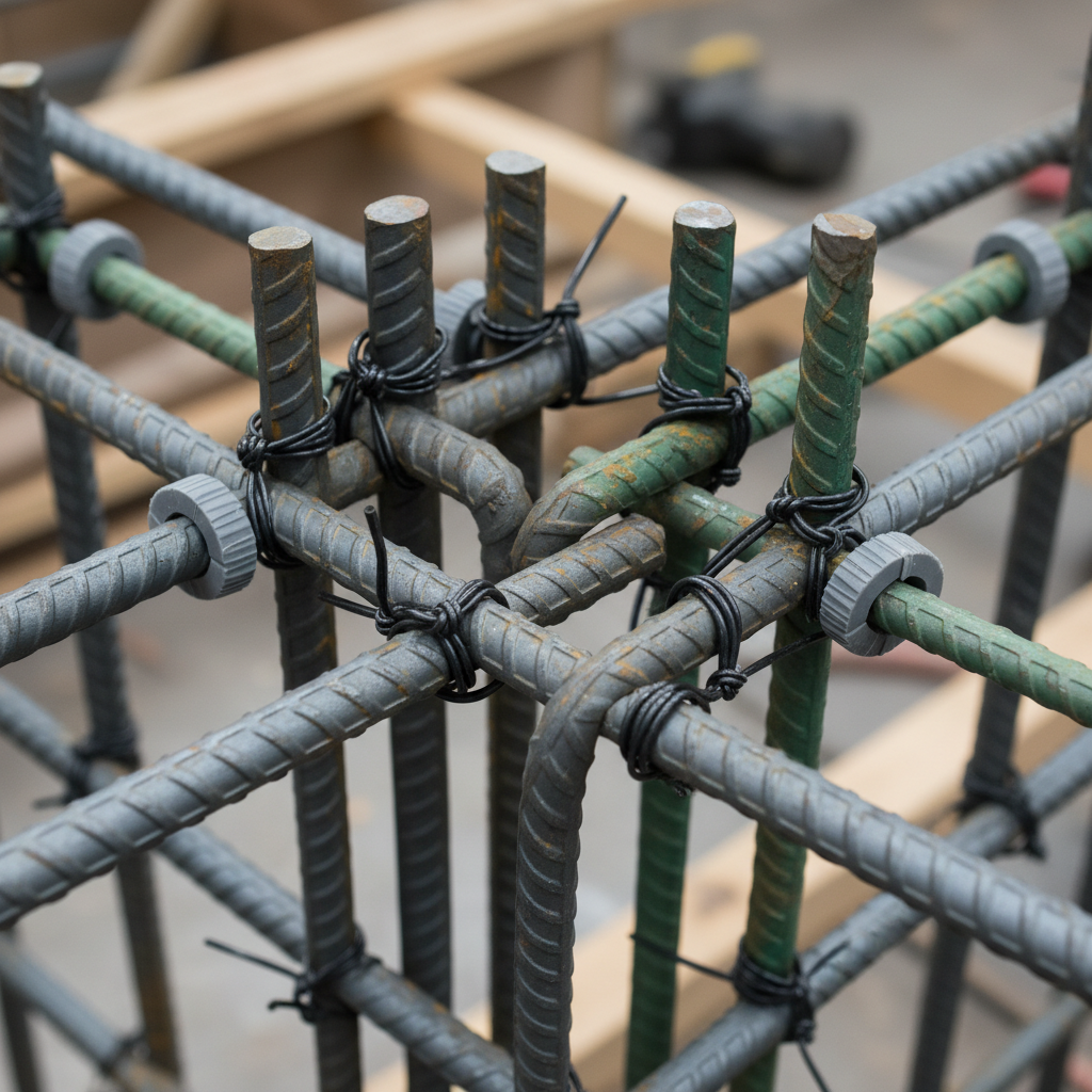
Foundation walls are detailed differently for cast-in-place concrete, ICF, or masonry. Corners, step footings, and openings require special bars and hooks. Waterproofing interfaces, sleeves, and pour joints must be coordinated in drawings to avoid conflicts.
Different wall systems drive different detailing choices. Here are the common ones you’ll encounter across GTA projects.
Cast-in-place concrete walls
- Typical spacing: Vertical bars at 12–24 inches; horizontal at 12–18 inches, adjusted for wall height and soil conditions.
- Corners: Use corner bars and extra horizontals (“U” bars) to control diagonal cracking.
- Openings: Add jamb and lintel bars with adequate laps around window wells and service doors.
ICF (insulated concrete form) walls
- Placement: Bars are threaded through ICF webs; watch cover at both faces.
- Bracing: Ensure horizontal bars don’t conflict with ICF ties; stagger laps.
- Consolidation: Maintain clear spacing for proper concrete flow and vibration.
Masonry foundation walls with grouted cells
- Vertical steel in cells: Positioned over dowels; grout lifts coordinated with bar lengths.
- Bond beams: Horizontal reinforcement at course intervals; use corner and tee bars.
- Interfaces: Align with slab dowels and waterproofing details to prevent thermal bridges.
Step footings and grade changes
- Step locations: Add development bars over each step and lap to the next elevation.
- Shear keys: When specified, align with wall steel to maintain continuity.
- Backfill timing: Don’t backfill until walls are cured and braced; coordinate with structural notes.
Need a refresher on common bar types by project stage? See our steel rebar basics and footing rebar guide for footing-to-wall transitions.
Best Practices That Prevent Callbacks
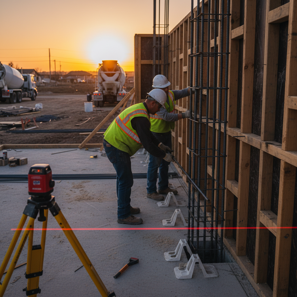
The best foundation rebar details are clear, coordinated, and constructible. Keep cover with the right spacers, avoid congestion at corners, stagger laps, and tag every bundle. Sequence deliveries to the pour plan so crews place steel once—not twice.
Use these practices to keep inspections smooth and pours on schedule.
Drawings that crews actually use
- One detail, one purpose: Place typicals beside each condition—corners, steps, openings.
- Consistent symbols: Keep rebar callouts uniform across plans, elevations, and sections.
- Field notes: State lap lengths, hook types, and cover in inches and millimeters to avoid confusion.
Material choices that last
- Epoxy-coated bars: Use at splash zones or where de-icing exposure is expected.
- Welded wire mesh: Consider for crack control in foundation slabs adjoining walls.
- GFRB (glass fiber bars): Non-corroding reinforcement for specific conditions; verify compatibility with the design.
Field-proven placement habits
- Stagger laps: Avoid stacking splices in one section; distribute along the wall length.
- Keep cover: Use chairs and spacers at 3–4 foot intervals to maintain face cover.
- Corner discipline: Add extra horizontal bars near corners and returns to resist diagonal cracking from backfill pressure.
Want a product snapshot? Our JDASS network provides a concise overview of reinforcing options on the rebar products page, helpful when you’re confirming availability of 10M, 15M, and 20M equivalents for a weekend pour.
Tools and Resources You Can Use This Week
Build a pre-pour checklist, a bar-mark index, and a delivery sequence sheet. Use simple templates to track covers, laps, and corner bars. Confirm that fabrication tags match the shop drawings before steel enters the forms.
Here are field tools we recommend and help our clients set up.
Pre-pour checklist (wall)
- Shop drawings approved and latest revision on site
- Bar marks checked against tag bundles
- Vertical spacing verified at 12–24 inches on center as detailed
- Horizontal spacing verified at 12–18 inches on center
- Laps measured to the drawing requirement (e.g., tension lap around 40db when specified)
- Hooks oriented correctly at corners and openings
- Cover maintained with chairs/spacers; no bars touching forms
- Penetrations and sleeves coordinated; waterproofing interface confirmed
Bar-mark index (quick reference)
- Mark, size (10M/15M/20M), cut length, bends, quantity
- Location (grid line range or station), elevation, lap requirements
- Bundle ID matched to delivery ticket for traceability
Delivery sequence sheet
- Footing steel first, then wall steel by pour area
- Staging zones on site to avoid double-handling
- Contact list: superintendent, foreman, detailer, dispatcher
If you’re formalizing your process, our reinforcing steel guide and Ontario rebar overview outline how estimating, detailing, and logistics fit together so inspections and pours stay predictable.
Case Studies and Examples (Ontario Focus)
Real projects show why clear rebar details matter. Coordinated shop drawings, labeled bundles, and sequenced deliveries reduce handling, prevent congestion at corners, and pass inspections with fewer corrections—especially on multi-pour basements and step footings.
Here are practical scenarios similar to builds we support across the GTA and Ontario.
Example 1: High-rise residential basement with jogs
- Challenge: Multiple step footings and wall returns created congested corners.
- Detailing move: Added U-bars at corners, staggered lap zones, and clarified hook orientations.
- Outcome: Pre-pour inspection cleared on first pass; backfill scheduled 7 days after strip per structural note.
Example 2: Mid-rise with elevator pit and sump
- Challenge: Penetrations and embeds risked cover loss around openings.
- Detailing move: Tightened bar spacing near openings, added jamb bars with full laps, coordinated sleeve clearances.
- Outcome: Pour ran without hold points; waterproofing crew began 48 hours after cure start as planned.
Example 3: Townhome block with ICF foundation walls
- Challenge: Maintaining cover in ICF webs and avoiding clash with ties.
- Detailing move: Specified staggered laps and spacing that respected ICF tie geometry.
- Outcome: Bar placement hit tolerance; vibration/consolidation zones stayed open for flow.
Example 4: Municipal building (infrastructure-grade)
- Challenge: Corrosion risk and de-icing exposure around grade line.
- Detailing move: Used epoxy-coated reinforcement at splash zones and increased cover at exterior faces.
- Outcome: Inspection accepted the protective measures; exterior face finish met spec.
Example 5: Garage addition with masonry stem walls
- Challenge: Aligning dowels from footings with vertical bars in CMU cells.
- Detailing move: Bar maps ensured every second cell received vertical steel; bond beams closed the system.
- Outcome: Grout lifts and inspection points were predictable; no rework.
For product reference while planning, our sister site offers quick overviews of framing and steel options that often intersect with foundation decisions, such as steel stud wall framing and a broader steel studs guide.
Design Tables and Rules of Thumb
Use rules of thumb cautiously and always follow the engineer’s drawings. Typical walls use 10M–20M (~#3–#6) bars at 12–24 inches on center with extra steel at corners and openings. Maintain face cover and stagger laps to avoid congestion.
The following table summarizes common, constructible patterns used on Ontario projects. Always defer to stamped drawings.
| Wall thickness | Typical vertical | Typical horizontal | Common bar sizes | Notes |
|---|---|---|---|---|
| 8 in | 12–18 in o.c. | 12–18 in o.c. | 10M–15M (~#3–#5) | Add corner U-bars; verify cover at both faces |
| 10 in | 12–24 in o.c. | 12–18 in o.c. | 15M–20M (~#5–#6) | Stagger laps; coordinate openings |
| 12 in | 12–24 in o.c. | 12–24 in o.c. | 15M–20M (~#5–#6) | Use chairs at 3–4 ft spacing to hold cover |
Need larger diameters or special coatings? Dass Rebar stocks Grade 400W/500W with epoxy-coated options and can source alternatives for specific exposures when the spec calls for them.
Quick Mid‑Project Check‑In (Soft CTA)
If your schedule is compressing, align detailing, fabrication, and delivery with one team. A single point of coordination reduces RFIs, accelerates approvals, and keeps pour dates intact even when jobsite conditions change.
Working in the GTA or broader Ontario and need help now? Our team can coordinate estimating, detailing, fabrication, and trucked delivery so crews place each bar once—and only once.
Frequently Asked Questions
These quick answers address the rebar details most crews ask about before pour day: lap lengths, corner bars, spacing, cover, epoxy use, and footing-to-wall dowels. Always follow your engineer’s stamped drawings first.
What’s a typical spacing for vertical bars in a foundation wall?
Common practice ranges from 12 to 24 inches on center depending on wall height, thickness, and soil pressure. Many walls use 15M (~#5) vertical bars with horizontals at 12–18 inches. Always follow the engineer’s drawings for your project.
How do I handle rebar at a wall corner?
Use dedicated corner bars and extra horizontal “U” bars to control diagonal cracking. Stagger lap splices around the corner and maintain cover with spacers. Hooks should be oriented per the detail so corner anchorage is achieved without congestion.
When should I specify epoxy-coated rebar?
Use epoxy-coated bars where corrosion risk is high—near grade lines exposed to de-icers, in splash zones, or where the specification calls for enhanced durability. Coordinate with the engineer to confirm coating requirements by location and exposure.
What’s the difference between 10M, 15M, and 20M bars?
They are Canadian bar designations roughly equivalent to #3, #5, and #6 in the U.S. 10M (~#3) suits light reinforcement; 15M (~#5) is common for walls; 20M (~#6) provides higher capacity where walls are taller or loads greater.
How do footing dowels tie into the wall reinforcement?
Dowels project from the footing into the wall to provide anchorage. They must have proper embedment, spacing alignment with vertical wall bars, and correct cover. Check that dowel sizes and spacing match the wall bar pattern before setting forms.
Key Takeaways
Great foundation walls start with clear, constructible rebar details. Keep cover and spacing, reinforce corners and openings, stagger laps, and coordinate deliveries. A single supplier–fabricator streamlines approvals, staging, and inspections so pour dates stick.
- Use clear drawings with explicit bar marks, laps, hooks, and cover.
- Vertical bars often 12–24 in o.c.; horizontals 12–18 in o.c. (per design).
- U-bars at corners and extra steel at openings prevent common cracks.
- Maintain cover with chairs/spacers and verify before pour.
- Coordinate fabrication and trucking to your pour breaks.
Local considerations for Woodbridge and the GTA
- Plan winter pours with heated enclosures and adjust sequencing; cold snaps can extend cure times and shift inspection windows.
- Account for spring thaws and high water tables; coordinate waterproofing details and exterior cover on walls facing persistent moisture.
- Use epoxy-coated steel at grade transitions and entrances exposed to de-icers; it’s a practical safeguard in busy urban sites.